by David Lloyd Klepper
Yeshivat Beit Orot, Shmuel ben Adiya 1, Mt. of Olives, Jerusalem 97400, Israel ddaveklepper1@gmail.com
I. Introduction
From the first day of my employment with Bolt Beranek and Newman, Inc., (BBN), 1 May 1957,1 until after my move to Jerusalem 11 July 1996, I worked assisting congregations reconciling the acoustical requirements for speech and music in worship spaces.2 Up until 1952 the reverberation time was considered the most important factor. Then, work by Parkin and Taylor in St. Paul’s Cathedral, London, using a delayed, distributed, tapered-line-arrays sound system to increase the direct-to-reverberant ratio, demonstrated the early-to-reverberant sound energy ratio’s importance, although they termed it the direct-to-reverberant ratio. Since then most authors have come to agree that the Early-to-Reverberant (or Late) Sound Energy Ratio, ELR or C50, is of prime importance, although the Initial Time Delay Gap TI also has a part to play.4,5,6,7,8,9 The effects of background noise are not included here but will be discussed in a future paper. All examples and analyses here assume background noise levels of NC-30 or less for lecture halls and NC-20 or less for theaters, as well as adults with normal hearing.10
This analysis is presented in honor of the memory of William Ranger Farrell, an early teacher of mine at BBN, who was willing to risk his own reputation by transferring responsibility of some of his own clients’ projects to me, despite my then relative inexperience, and who was on the cutting edge of speech privacy acoustics research, including the development of masking noise systems.11, 12 After leaving BBN to start his own firm, he was also helpful to L. Gerald Marshall, Larry King, and me, when we inaugurated Klepper Marshall King, Associates (KMK) in July 1971.
II. The Parkin-Taylor Concept comes to America
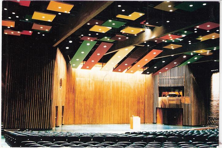
Figure 1 is a photograph of interior of Boston’s historic Holy Cross Cathedral (Roman Catholic). In the summer of 1954, the Boston Diocese decided the existing sound system should be replaced, and asked DeNambro Radio and Supply to provide a proposal. DeNambro turned to BBN for design assistance. Dr. Leo Beranek had heard of the St. Paul Cathedral installation and proceeded to ask DeNambro to provide a test system, based on the St. Paul design. Design considerations precluded the addition of sound-absorbing material to reduce the Cathedral’s reverberation time in deference to the musical portion of Cathedral worship, a consideration parallel to that at London’s St. Paul. Figure 2 shows the system’s basic design and that of the system that was finally installed thirty-five years later, based on that design.13,14
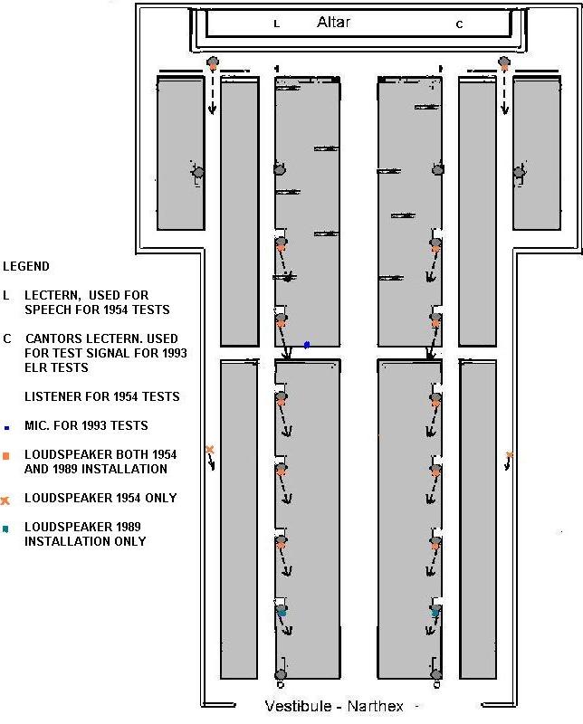
Figure 2
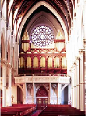
Figure 1
Figures 1 and 2. The interior of Boston’s Holy Cross Cathedral looking to the rear and to the choir gallery with the Hook and Hastings 1875 organ; and the loudspeaker plan for L. L. Beranek’s 1954 test system and the 1989 installation. Organ CDs available.
In the autumn of 1954, I was an M.I.T. graduate student in Dr. Beranek’s Electroacoustics course. Our class became the test subjects for intelligibility testing, and these tests left an important impression on me. The experiment was a success, but for whatever reason, the Diocese decided not to proceed with a permanent installation at the time.13
Part-time employment at the MIT Acoustics Laboratory, 1956-1957, while working towards my Masters Degree, allowed its Director, William Kessler, to introduce me to the organist at Christ Church Cambridge, Marion Boron, for recording some of her performances. Through Marion, I made the acquaintance of people at the Aeolian Skinner Organ Company (AS) and was able to sit in on rehearsals and recording sessions both at her church and at Boston’s Church of the Advent. Alfred Nash Patterson was the Music Director at Advent, and Charles Allan Romeo his assistant. I was overcome with the beauty of the sound of the AS organ in the reverberant acoustic environment of that church. I thought the sound the most beautiful I had heard, rivaling even the Boston Symphony in Symphony Hall. But at the Acoustics Laboratory and at BBN, an often-repeated joke was: “The Church of the Advent wants us to improve speech intelligibility, but doesn’t want us to change the acoustics.”
I decided a misconception needed fixing and requested a job interview with BBN. In it, I pointed out the applicability of the 1954 experiment to the Church of the Advent’s problem, that by “acoustics,” the church people were referring to the music acoustics and not the speech acoustics, and that good sound system design could provide speech intelligibility in the reverberant space. So, I was hired, and Frances Weiner gave me the fast education I needed in terms of what loudspeaker technology was available in practice (primarily from Altec Lansing at the time) to control amplified sound in a manner to minimize reverberation.2
The first opportunity I had to apply this idea was not at Advent, but at the Westfield, New Jersey’s First Methodist Church. Wilma Jensen was the Organist and Music Director there, and she hoped that intelligibility could be improved without adding sound-absorption to reduce the reverberation time. The church had completed an installation of both an AS organ and a new sound system. The sound system used multiple Altec (Western-Electric-designed) 755A loudspeakers along the side walls, excellent loudspeakers, but misapplied. I recommended replacement of the side-wall-mounted loudspeakers by one Altec multicellular horn, aimed to both minimize sound-energy directed to sound-reflecting wall and ceiling surfaces and also to provide even coverage of the congregation, thus increasing the ratio of early-to-reverberant sound energy. Figure 3 shows indicates that “my” multicellular horn has been replaced by a curved-line-source loudspeaker system, capable of wide-frequency-response music reinforcement as well as speech, and also of providing approximately the same directional control of amplified energy that the multicellular horn did.
Figure 3. The interior of Westfield, New Jersey’s First United Methodist Church. Installation of an Altec multicellular horn central loudspeaker at the top center of the chancel arch made installation of sound-absorbing panels unnecessary, but has been replaced with a newer system with similar direction sound propagation control.
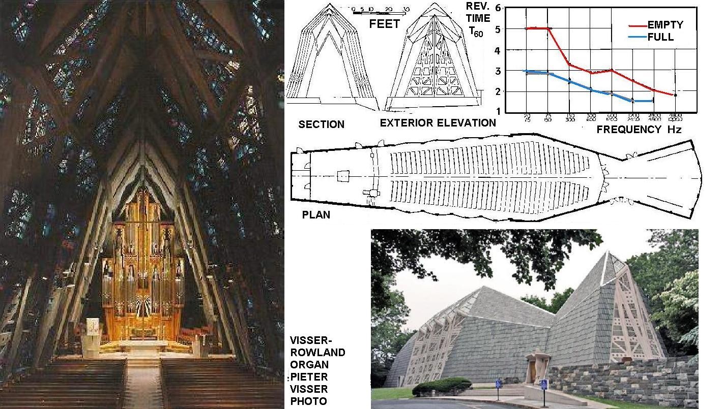
Figure 4. The interior of Stamford, Connecticut’s First Presbyterian Church, looking forward to the Visser-Rowland pipe organ, plus the plan, two cross-sections, and the church’s measured reverberation time characteristics.15, 16
The First Presbyterian Church, architect Wallace Harrison’s “fish church,” was evaluated acoustically by the author with the assistance of Howard Rockstrom, although Robert Newman and W. Ranger Farrell served as consultants in the design and construction. Intelligibility was good with a two-second reverberation time and without either sound-absorbing treatment or the use of a sound system. This did not stop two congregants from selling the church on the idea of a sound system with loudspeakers under the pews, a poor choice since more reverberant than direct sound usually reaches listeners’ ears, and then on sound-absorbing panels to mitigate the added reverberant energy produced by the sound system. All this was removed from use with the installation of a new Visser-Roland pipe organ several years ago, replacing the original landmark Allen electronic. In my paper evaluating the church’s acoustics, I used the words “direct sound” where early sound would have been correct.15,16 See Figures 4 and 5.

Figure 5a.

Figure 5b.
Figures 5a and 5b. Pew-back sound systems work reasonably well in reverberant spaces because only a small portion of the loudspeaker radiated sound undergoes multiple reflections to excite the room reverberation. Under-pew loudspeakers do not work well in reverberant spaces, because a high proportion of sound energy undergoes multiple reflections under the pews and is randomly radiated to ceiling and wall surfaces for further multiple reflections.
Much of this work, including other projects of the period, were done with the basic concept in mind, but no real theoretical underpinning other than that presented in the Parkin-Taylor St. Paul Cathedral Wireless World paper.3 Of course, there were other workers in the field that had read that paper, and/or been a student in Dr. Leo Beranek’s class at the time of the Holy Cross Cathedral experimental sound system installation. But the basic concept did take hold at BBN, and allowed confident planning for concert halls with the assurance that speech intelligibility would be provided by well-designed sound systems. An example of the application of this approach was the multicellular horn sound system installed in Cloughs Hall, Butler University, Indianapolis.17 While Russell Johnston, then at BBN, was responsible for the room acoustics (Evans Woolen the architect), Bill Hanley was responsible for both the design and installation of that sound system. One of Robert Newman’s important teachers at the University of Texas, Dr. Paul Boner, became famous for his extensive use of narrow-band equalization, but he also used directional control of loudspeaker energy to provide intelligibility in reverberant spaces.18 My own major concert hall project at the time was the Dartmouth College Hopkins Center Spaulding Auditorium, used as both a lecture hall and concert hall. John Volkmann of RCA had visited BBN, provided accurate data on the performance of RCA radial directional horns, and this equipment was used at Dartmouth, after a specification permitting either Altec or RCA equipment. Harrison and Abromovitz were architects, with Walter Colvin as job captain. See Figure 6.
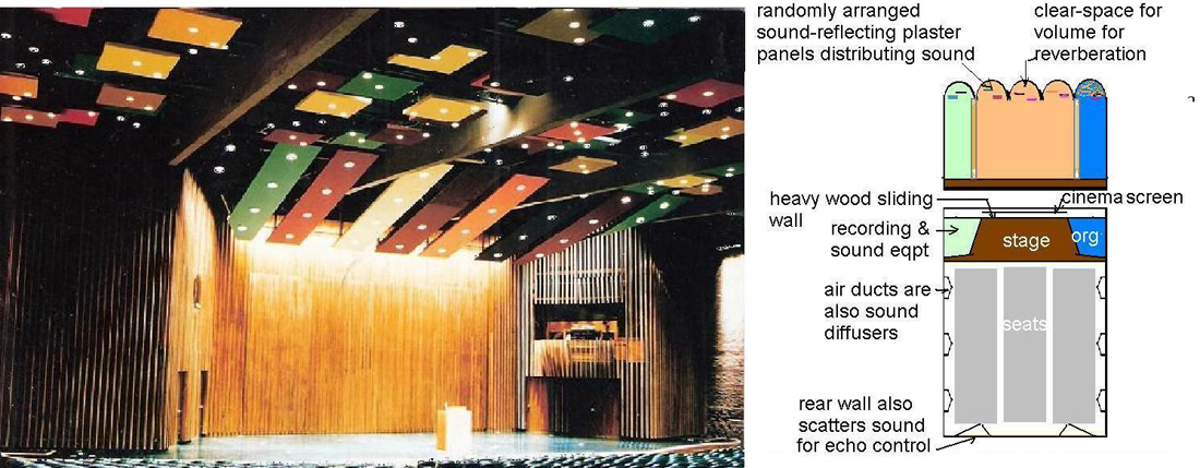
Figure 6. Spaulding Auditorium, at Dartmouth College’s Hopklns Center. The main sound-reinforcement system’s directional characteristics allow all surfaces that can be hard and sound-reflecting to be left untreated with sound-absorption. A sound-transparent grille is located where panel down-lights appear to be missing, and the RCA loudspeaker equipment for reinforcement is located above and behind. The hall is used successfully for both concerts and lectures.
III. Theory catches up to Practice
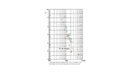
The earliest proponents of the metric Clarity as important for Room Acoustics were the Europeans: W. Reichardt, U. Lehmann, and J. H. Rindel, among others.9 In North America, J. Bradley, A. C. Gade, G. W. Seibein, and J. R. Hyde all made contributions.22 But the idea is not without its critics. V. M. A. Peutz based intelligibility estimates on reverberation time, modified by consideration of the directivity of the sound source, the equation modification provided by W. Klein for the ratio of sound energy reaching the listener directly to the average that would result if the source were omnidirectional, and of course the distance from source to listener. If the first reflection is louder at the listener than the direct sound, then it replaces the direct sound in calculations.6,19 Neglecting background noise and considering just room-acoustics, this concept is a marked improvement over reverberation time only, and has provided dependable correlation with intelligibility testing in many tests, especially involving comparisons between loudspeakers and loudspeaker systems with varying degrees of directional control.21,30 The equations and the developments dating back to Knudson and Harris are discussed thoroughly in the Marshall Long references and are not repeated here.6 Figure 7 is developed from that reference and is possibly the most useful way to their application. Generally, calculations are done for the 2000 Hz octave-band, or for weighted summation 15% 500 Hz, 25% 1,000 Hz, 35% 2,000 Hz, and 25% 4000 Hz (L. Gerald Marshall’s weighting7). Figure 8 shows why this is the preferred frequency range to evaluate speech intelligibility.21
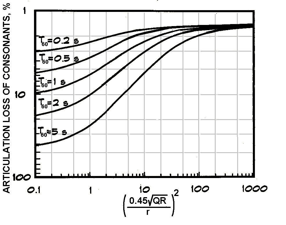
Figure 7. Peutz’s and Klein’s determination of the Articulation Index from r, the distance in meters from the sound source, Q, the Directivity of the sound source in the direction of the listener, R, the Room Factor or the total absorption in the room in Metric Sabins, also noted elsewhere as aT, and the Reverberation time T60.6,19
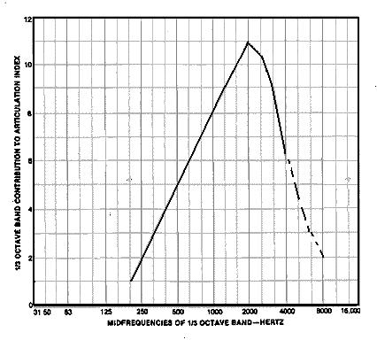
Figure 8. Michael Rettinger’s analysis of the contribution of each 1/3-octave-band to speech intelligibility, probably based on work by French and Steinberg, as transmitted to Don and Carolyn Davis.21 The total, if the numbers are treated as percents, comes to a total of 90.5, and one may question where the remaining 9.5% is. Nevertheless, it seems a reasonable evaluation. The dashed lines are this author’s speculation as to where the additional 9.5% may be found.
I and others have found this procedure difficult to use in evaluating architectural modifications, such as tilting a sixteen-foot, or five-meter-high ceiling over a lecturer’s platform or adding an appropriate pulpit canopy in a worship space. In both cases early reflections are increased in strength and/or number, and the reverberant energy is reduced, without noticeably reducing the reverberation time. The objections of those who deny fusion of early sound for intelligibility was first presented by C. R. Cable and R. C. Emerson, using only electroacoustics testing.22 The idea is that any specific early reflection may be destructive as easily as constructive because of phase interference. What are missing from their reasoning is first that the wavelengths of the frequencies that contribute most to speech are less than the distances between one’s ears, and that path-length differences of the reflection to the two ears are certain to insure that absolute cancellation seldom occurs in both ears, and even then only instantaneously (refer to Figure 8), and second, in the real world, heads continuously move slightly for both talkers and listeners, and the random spread of reflections in real world rooms also eliminates phase cancellation as destructive of the added benefit of early reflections. Don and Carolyn Davis have written in support of Emerson and Cable, but the have been very honest in presenting the backup data.21 What they may not have known at the time their test were made (I participated and probably operated the TEF equipment) was that the Articulation Loss of Consonants numbers that the Crown TEF-20 equipment was giving them were based entirely on the C50 early-to-reverberant sound energy ratio. Their experiments were all with regard to loudspeaker propagation, not room design, and the Peutz-Klein concept both worked well in that application and substantially agreed with the Crown TEF readings. And both agreed with our subjective evaluations. One can predict that the agreement would not have resulted if the comparisons concerned architectural modifications instead of loudspeakers with different directional characteristics. Quoting L. Gerald Marshall, “The great differences between natural room acoustics response and recording system response underscore the possible pitfalls in using synthesized sound fields and loudspeaker reproduction for research relating to room-acoustics criteria.”7
Mention must also be made of the research of the South Africans J. P. A. Lochner and J.F. Berger, who developed a sliding scale for reflections from 35 millisecond delay to 95 milliseconds after the direct sound, with energy just over 35 milliseconds possibly harmful under certain conditions and energy just under 95 milliseconds helpful.23 This was discussed by J. Jacek Figwer in the development of an early analogue system to display the required information, but graphical analysis by hand was still required.24 Hard work from experience in summer of 1967 at BBN. In any case, the South Africans and Jacek Figwer agree fusion of early sound for intelligibility exists. Essentially, the C50 concept represents a practical compromise implementation of the Lochner-Berger-Figwer work that will be applicable in a majority of situations where architectural acoustics and/or sound system measures are to be implemented. The known cases where it must be modified to be applicable will be discussed.
IV. Early Decay Time
The time required for sound to decay only ten deciBels instead of sixty deciBels, times six to make the numbers comparable with normal reverberation time, T10, has considerable acceptance as an important metric in concert hall acoustics abbreviated as EDT, and occasionally crops up in discussions of speech intelligibility. As discussed in the concert hall clarity paper on this website, I find it less important than Clarity and even possibly superfluous if Clarity, C80 for concert halls, is a design consideration and is measured. An illustration of why it may not be particularly applicable in real situations, or at least situations outside of normal concert hall designs, is illustrated by data taken by Jacek Figwer at the First Baptist Church of Chattanooga, Tennessee. As seen in Figures 9a and 9b, analyzing for EDT is problematical in the case of unaided voice, without sound reinforcement, Figure 9a, because the lack of early reflections gives an EDT of close to zero time. Adding early sound from a distributed and delayed building-column vertical line-source loudspeaker systems, Figure 9b, adds useful early sound, makes a poor intelligibility situation into a good one, and at the same increases the EDT instead if decreasing it! On the other hand, Clarity measurements would show the improvement the use of the sound systems provides.
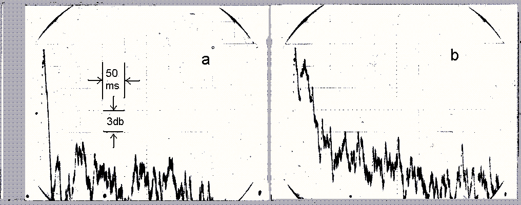
Figure 9. 0sciliscope traces of 1,000 Hz filtered and integrated response to an impulse at the First Baptist Church, Chattanooga, Tennessee, without the sound system, a; and with the sound system, b. The slope of the direct sound is probably more determined by the integrating process and the oscilloscope characteristics. The photographs have been reversed in color, enhanced in contrast, and scale numbers added.24
Why is a sound system required for speech intelligibility in this church, given the drop of 13 db from direct to reverberant sound levels? The answers are the large building, over 600,000 cu. ft., and the three-second reverberation time, which does not show up in the oscilloscope traces that see less than half a second of the decay process.23
V. Usefulness of C50
Richard K. Heyser took the developments of audio digital delay devices and the progress in computers to develop ‘Time-Delay Spectrometry,” a powerful measuring technique that can provide much useful information on room acoustics and sound system behavior, as well as other uses in areas of sound-isolation and vibration control and analysis.20 Using this technology, Crown Corporation developed the TEF (Time, Energy, Frequency) analyzer, and L. Gerald Marshall assisted in their developing a program that made measurements of Clarity (as ELR, Early-to-Late Ratio) straight-forward without requiring a truck-load of equipment. I found this technology invaluable in identifying problems or confirming the existence of problems otherwise evaluated through listening, and in demonstrating improvement once the problems were solved.7 Some examples of its use follow.
Re-angling sound-reflecting side-wall and ceiling panels in a theatre
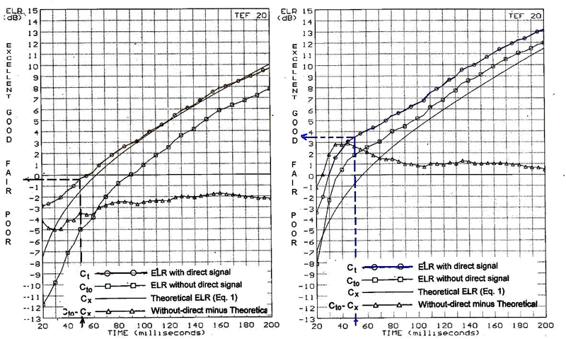
Figure 10. Crown TEF display before (a) and after (b) theatre panel adjustments7
One of L. G. Marshall’s consulting projects produced the before and after TEF-20 readouts of Figure 10 above, copied from Figure 9 of Reference 7-bottom. Added are his subjective intelligibility ratings (poor to excellent) of that reference’s Figure 8 and the dashed marker lines and arrows. The improvement shown was provided by re-angling wall and ceiling sound-reflecting surfaces. Since our concern in this paper is with the overall C50, or ELR for speech, the reader interested in the usefulness of the other Figure 10 curves, other than the ELR curves, is referred to the references. They can be valuable in identifying problems, and even in determining approximate directivity of a central sound system when such is used. The associated equations are in the references. The panel re-angling produced a four deciBel improvement for speech in the ELR, or C50, which can also be considered a signal-to-noise ratio. The C50 rating and L. G. Marshall’s assignment of adjectives can be explained from Figure 11 drawn from material in an article by Peter Mapp in Sound and Communications Magazine.30 Marshall’s subjective ratings are more favorable on the good side. P. Mapp’s article also discusses other speech intelligibility metrics, such as the Speech Transmission Index and the Rapid Speech Transmission Index for those interested. Here, we are focusing on C50.
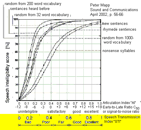
Figure 11. Expected intelligibility test scoring vs. C50 tests. Data obtained from various sources and integrated by Peter Mapp.30 Peter Mapp should be thanked and congratulated for assembling data from different sources to provide needed correlations. However, the author takes responsibility for the yellow shaded addition, good only for normal English conversation with normal hearing.
St. Thomas Episcopal Church, Fifth Avenue, New York City
St. Thomas was not the first church to employ pew-back loudspeakers, and that honor belongs to the Chapel at Oklahoma State University, Oklahoma City. for which Pietro Bellusci was architect (1967). It was not the first with a delayed pew-back system, and that church was the National Presbyterian Church in Washington, DC, for which Harold Wagoner was architect (1969).2 But it was the first to use a digitally delayed pew-back system, and has one of the two very first systems to employ digital delay world-wide. The other sound system was the Walnut Street Theatre, which supplements a proscenium sound system with delayed balcony and underbalcony distributed loudspeaker coverage. A Lexicon delay unit was used at St. Thomas, and an Industrial Research unit at the Walnut, both in 1971. Delay settings of both systems were fine-tuned by ear, TEF evaluations came later.
St. Thomas was constructed in 1913 with a design similar to a French Gothic cathedral with Ralph Adams Cram as overall design architect and Bertram Grosvenor Goodhue the interior details . Long reverberation times were considered a problem, and thus the ceilings were treated with an artificial porous stone, Raphael Guastavino’s “Rumford Tile.” My two partners and I were charged with both making this material sound-reflecting, so that the music performed and congregational singing could be supported by the natural reverberation that the visual appearance of the church indicated was appropriate, and at the same time insure high speech intelligibility. With the church authorities educated as to the possibilities of clarity in reverberant spaces, some successful pew-back systems already in operation, and the earlier recommendation by the great organ builder, G. Donald Harrison for a pew-back speech-reinforcement system, a go-ahead was received. There was some apprehension over the then experimental nature of digital audio delay, but our confidence in the abilities of the two manufacturers was transmitted to the church authorities. A for-bid specification was prepared, and the New York firm Commercial Radio and Sound was awarded the contract. Some RCA and NBC officials were church members, and the engineers at RCA Laboratories in Camden, New Jersey, expressed disappointment that they would not be supplying one of their acoustical pipe-delays. Most of the electronic equipment, including the original delay equipment, has been replaced over the past 43 years, but my partner in design, Larry King, has remained involved. The system has proven useful in reinforcement of harpsichords and clavichords, as well as speech.25,26
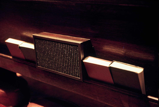
Figure 12. Typical pew-back loud-speaker enclosure at St. Thomas Episcopal Church, Fifth Avenue, New York City.25
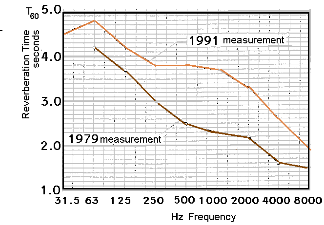
Figure 13. Reverberation times before and after application to the ceiling of four coats of Kyanize L-0560 sealer and one coat of L-0561 flat finish, a few years after the pew-back sound system installation.25 Music CDs are available.
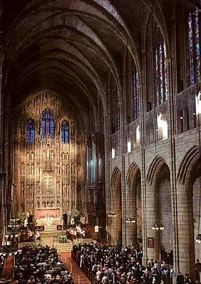
Figure 14a.
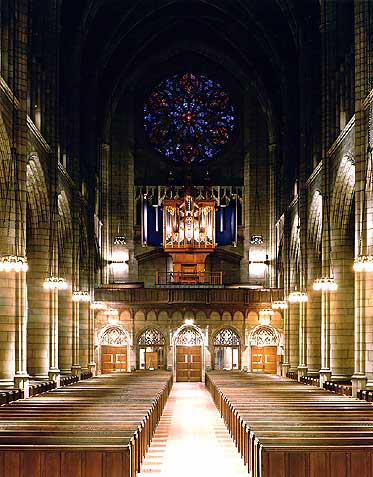
Figure 14b.
Figures 14a and 14b. St. Thomas Episcopal Church, Fifth Avenue. Left, view toward the Chancel and right toward the rear balcony and its Taylor & Boody Bach-period organ.25,26
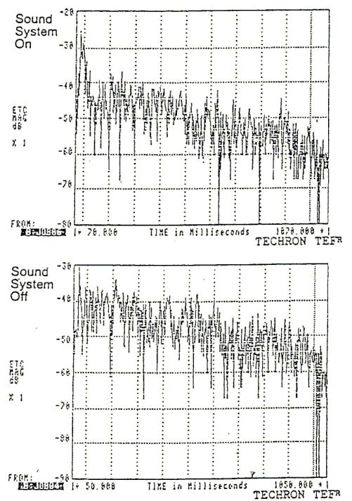
Figure 15. 1.000 Hz Octave-Band energy-time-curves for St. Thomas Church in 1991, top with sound system, bottom without sound system. The top curve is depressed 20 dB in absolute level with respect to the bottom curve. Apologies are in order for inconsistency in data presentation, which preferably would all be with the 2,000 Hz octave band. The 1991 data was taken during the TEF development stage, and I am using only the data available to me at this time.
St. Thomas Episcopal and Holy Cross Cathedral Similarities
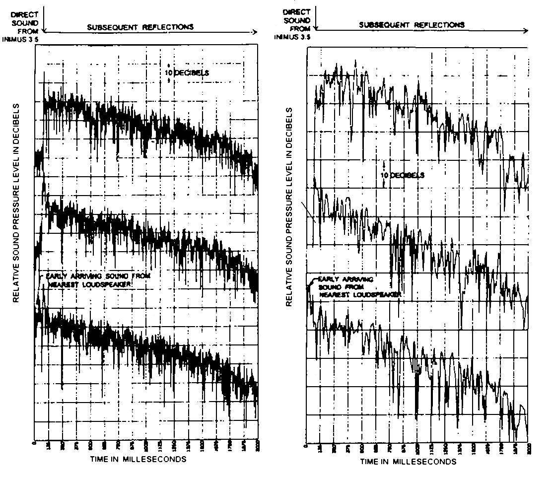
Figure 16. Octave-band energy time curves for Holy Cross Cathedral, left, 2000 Hz, right, 500 Hz. Top without sound system, middle sound system with optimal delay settings, and bottom with delays switched off.
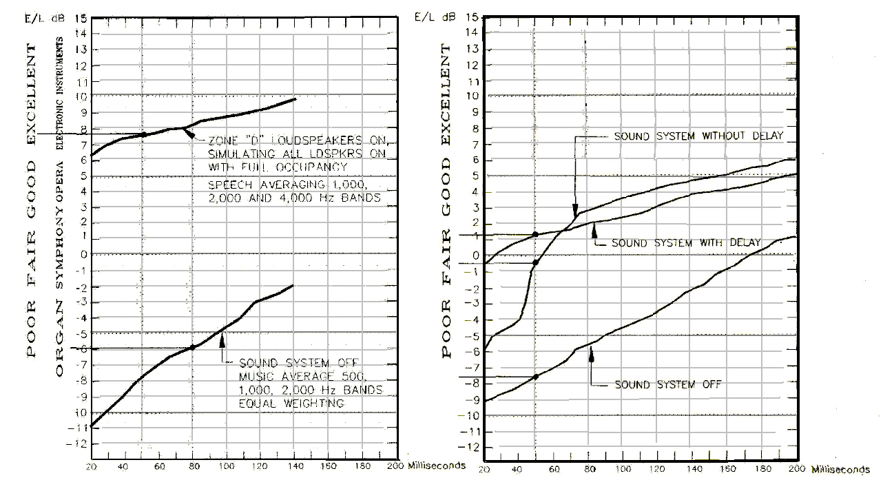
Figure 17. Crown ELR displays, St. Thomas Church left, Holy Cross Cathedral right. Subjective ratings and their pointers to the 50ms. (one case 80ms.) points added, speech weighting unless otherwise shown.
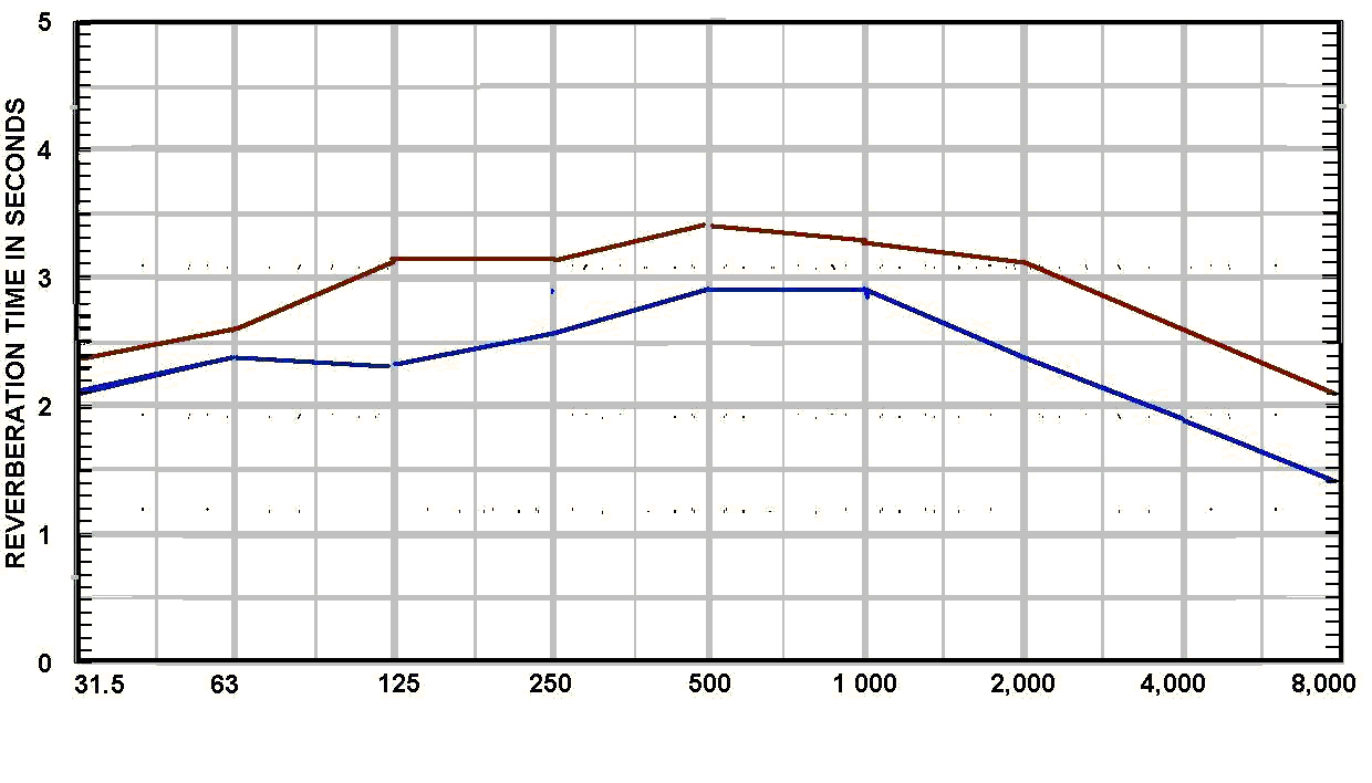
Figure 18a.
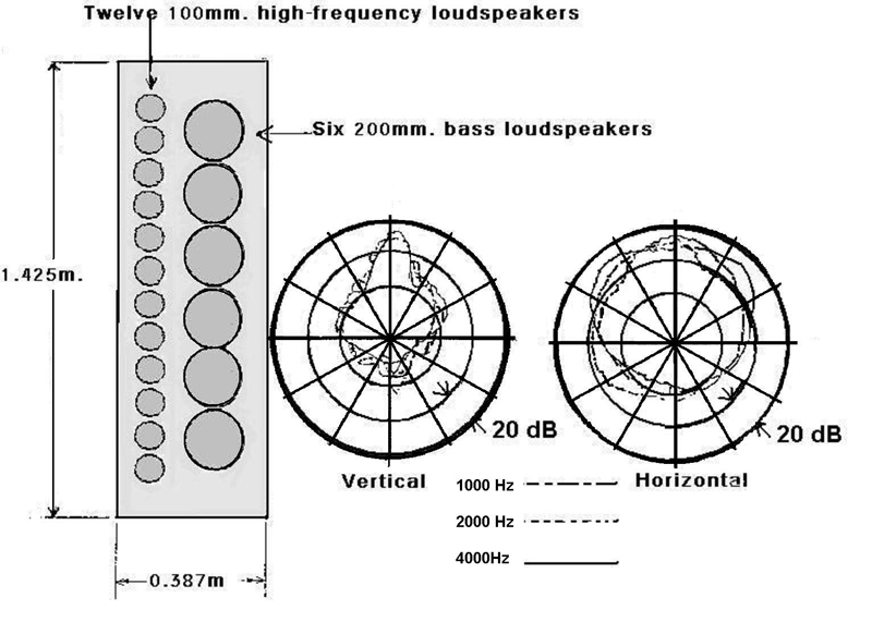
Figure 18b.
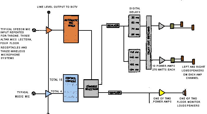
Figure 18c.
Figures 18a, 18b, 18c. More Holy Cross Cathedral information. Figure 18a, measured reverberation time characteristics, upper curve empty and lower curve full. Figure 18b, description of the Bozak 888 column loudspeaker used. Figure 18c, simplified sound system functional diagram. The vertical line represents bridging outputs from the preamplifiers to Boston Catholic Television’s separate control console.
Trinity Episcopal Church, Wall Street
The pew-back sound system in this historic church was designed by Edward Seeley, who had been Altec-Lansing’s Chief Engineer for many years, and consulted on sound systems after retiring from that position. Our firm was responsible for the first electronic upgrade, to simplify sound system operation and to replace the Ancha Electronics acoustical tube delay unit with a digital electronic delay. This was the first distributed sound system where we used the Crown TEF-20 equipment to set delays. In general, we found the delays that Ed Seeley had chosen were correct, but there were minor adjustments that made for some slight improvement in acoustical performance. There were no changes to the loudspeakers, Altec 405A, or their locations.
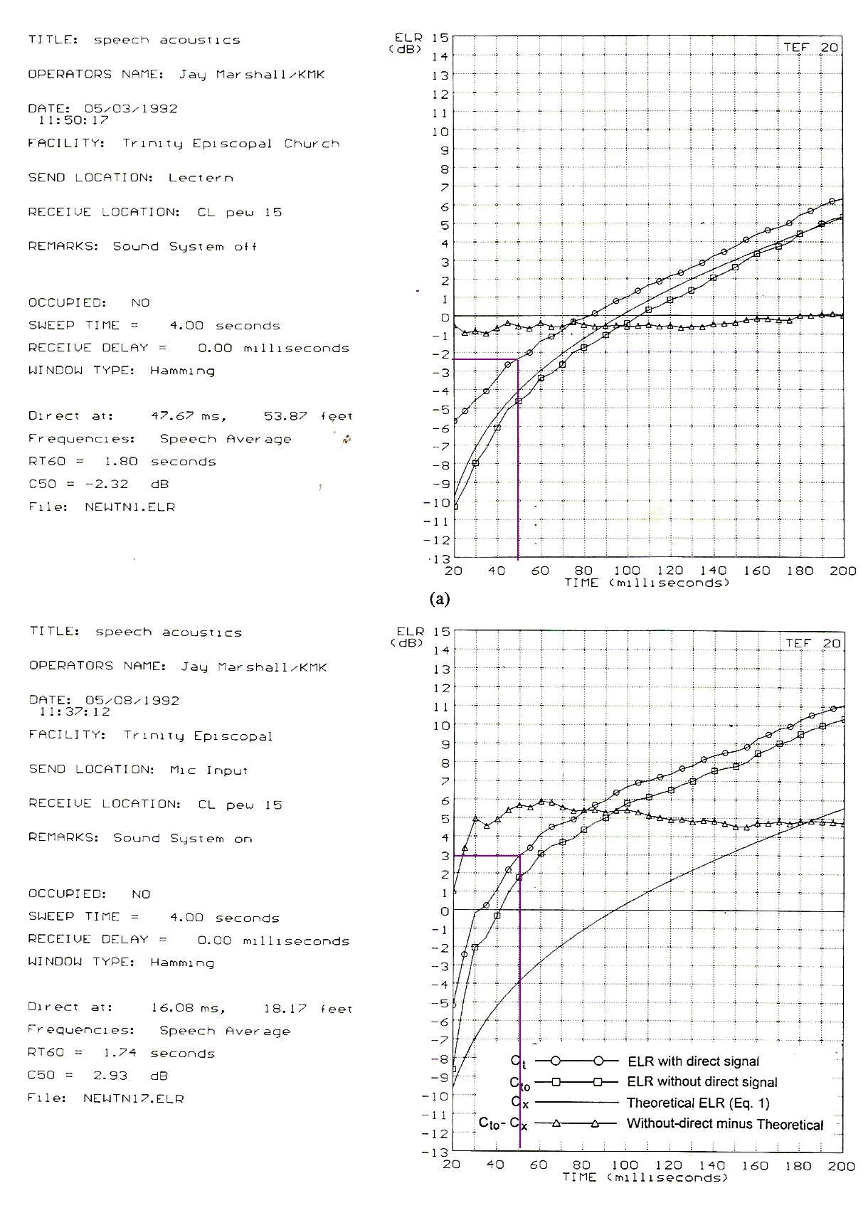
Figure 19. Two typical ELR TEF-20 speech average displays from Trinity Church, Wall Street. Top without sound the sound system and bottom with the sound system. The sound system moves the ELR or C50 ratio from -2.3 to 3, from poor to good.7 Music CDs are available.
VI. Echo Considerations
The work by Bolt and Doak, based on work by Karl Haas, suggests that if there are no useful reflected or loudspeaker signals received in the zero to 38-50 millisecond range after the direct signal, a strong signal more than 38 milliseconds late, that with “fill-in” in the 0 – 38 time span would be useful for intelligibility, may instead be heard as an echo situation. So, Dr. Leo Beranek’s placing The Initial Time-Delay Gap, t1, as important for music acoustics,29 should also be extended to speech acoustics. However, any t1 less than 38 ms. appears satisfactory.
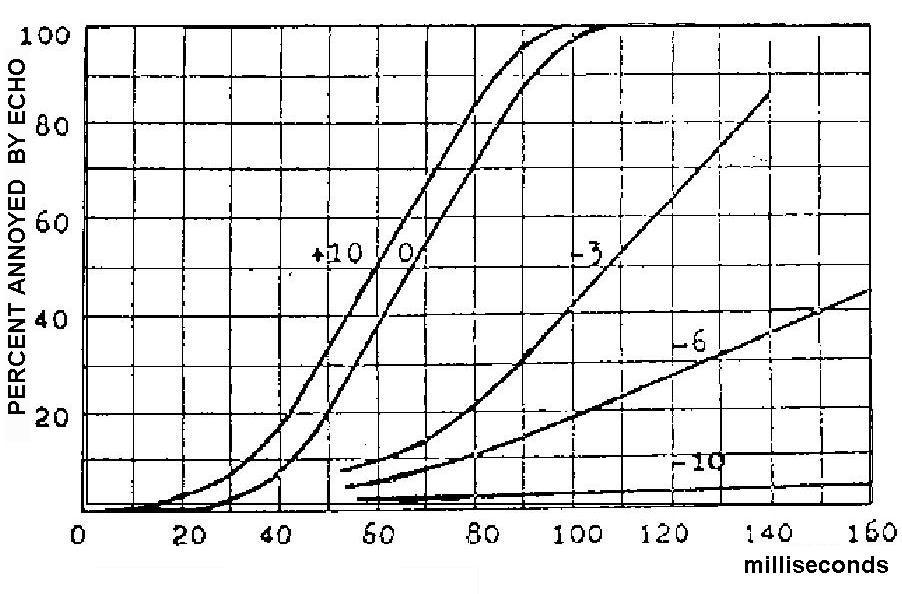
Figure 20a.
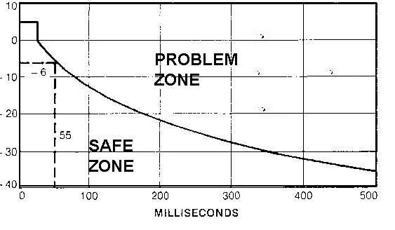
Figure 20b.
Figures 20a and 20b. The graph in Figure 20a displays Karl Haas prediction of echoes, with the numbers in the graph indicating the relative strength of the reflection to the initial signal. The graph in Figure 20b displays the suggested criteria by Bolt and Doak for speech reinforcement room design. The left-axis again shows the relative strength of the first reflection to the initial signal.27,28
VII Suggestions
a. Line of Sight
The speech reinforcement loudspeakers should always have direct line-of-sight to listeners. Figure 21 represents an exception, Uhlein Hall, Milwaukee, Harry Reese, architect, BBN, acoustical consultants, with Peter Tappan as sound system designer. George Izenour was theatre consultant. With the flying top balcony architectural configuration, listeners at the rear under that balcony, in the second-from-the-top balcony, received speech reinforcement signals from a reflection off the sloping main ceiling overhead. An analysis for C50 should place that reflection as the initial sound, and not the much weaker direct signal. Similarly, if the direct signal is 10 dB or more below the first sound system signal, the sound system signal should be considered as the direct signal for C50 analysis. The Uhlein system worked for speech reinforcement. But increasing demands on uses of the system eventually did result in the addition of delayed underbalcony loudspeakers for those seats.
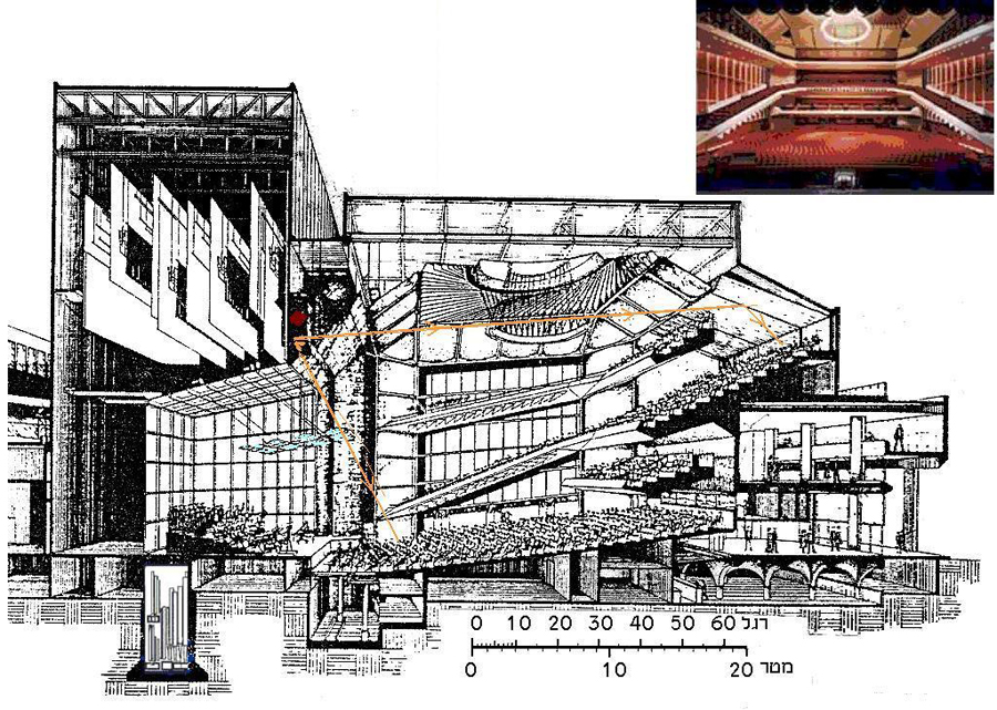
Figure 21. Uhlein Hall, Milwaukee, showing how listeners in the rear of the second balcony received speech reinforcement from the central loudspeaker system by reflection off the sloped rear ceiling overhead. For clarity analysis, the reflection should be treated as the initial sound. The hall does have delayed underbalcony loudspeakers now because of increasing sound system uses. Drawing from G. Izenour, Theatre Consultant. Photo from the hall’s website
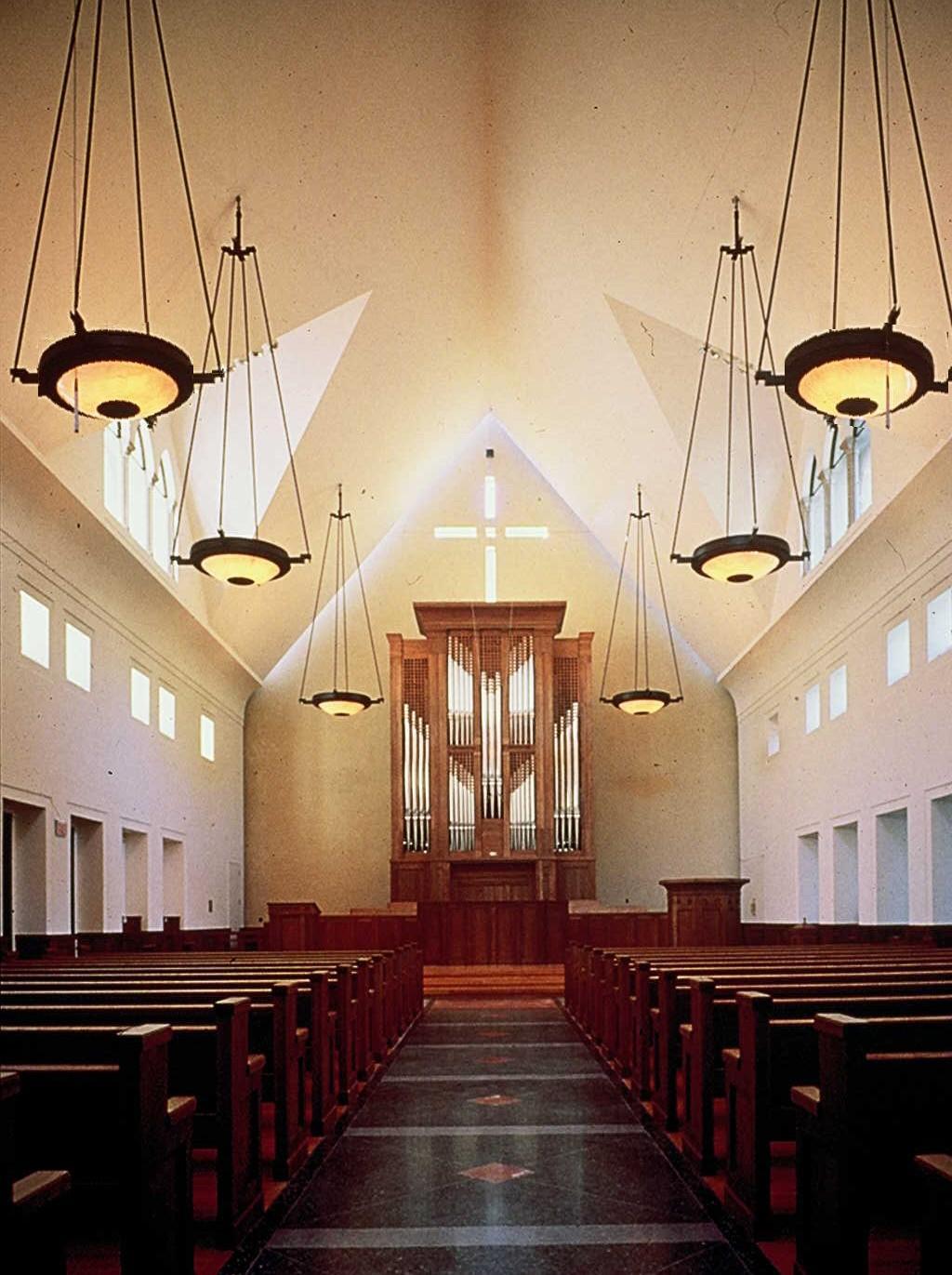
Figure 22. Hitchcock Memorial Presbyterian Church, Scarsdale, New York. The loudspeaker enclosures are integrated into the light fixtures. Larry King designed the sound system, and L. Gerald Marshall noise control and room acoustics, designed for the highest possible music quality, with speech intelligibility insured by the delayed distributed sound system. Photo, the author, Music CDs are available.
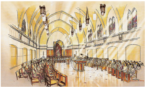
Figure 23. Mt. Saint Mary’s Church, with a delayed distributed loudspeaker speech reinforcement system. The white cylinders are the loudspeaker enclosures. Chandelier mounting reduces the area covered by each loudspeaker, insuring that time differentials in overlap zones are not excessive. Marshall Long was sound system designer and acoustical consultant. Controls permit coverage to be restricted only to occupied pew areas. From M. Long, Acoustics Today, March 2011.
b. Arrival Times
The difference in arrival times from two different loudspeaker systems in overlap zone should never be greater than 35 ms. and should be held to not more than 25 ms if possible. This has important implications for zoning in church pew-back systems, with no more than three rows grouped together. Rooms with high ceilings must use chandelier mounting for overhead distributed loudspeaker systems or use downward pointing directional horns to limit coverage to defined areas.
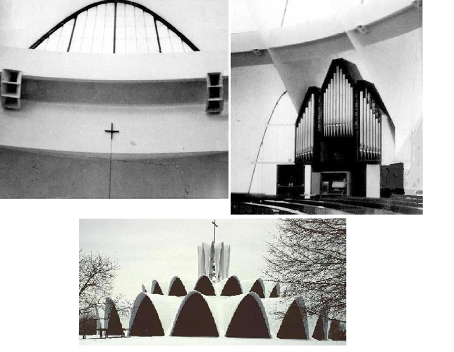
Figure 24. St. Louis Priory Church, now the chapel of a boys’ school. Hellmut, Obama and Kassabaum were architects and BBN acoustical consultants. The system may have been replaced by a pew-back system. The organ is by Rhedetsky. There is a similar horn distributed system at St. Norberts Abbey, De Pier, Wisconsin, with a traditional high-ceiling, rectangular-plan building.2
c. Test Equipment
There is a lively second-hand market in TEF-20 test equipment, Eastbay, etc. More modern equipment, some not requiring a separate computer for data acquisition, is available from Bruel and Kjaer, DRA Labs MLSSA, etc. Most will measure other metrics as well, including T60, Sound Pressure Levels in octave and 1/3-octave bands, and STI.30
d. Design Procedures
The modern computer programs available from several manufactures can usually be relied on to predict intelligibility or at least predict that a design will be satisfactory for all but very unusual uses. This is particularly true for the programs associated with steered array multi-element loudspeaker systems. The John-Prohs-David-Harris PHD loudspeaker selection and orientation program gives the user a choice as to consideration of close-in-time reflections as useful by manually entering the proportion of radiated sound as useful if one chooses to do so. Possibly my safe course can be recommended, to design the sound system as if only the direct sound is useful but evaluate it on the basis of a regular C50 test program and possibly also STI to meet legal requirements.
Designing room for natural reinforcement of speech intelligibility is a learned art, that is difficult to reduce completely to mathematical formulas. In a reverberant church, the improvement in C50 due to the addition of well-designed pulpit canopy might be six decibels, three for the reinforcement, and three for reducing the level of the reverberant field. Four or five dB is probably more likely.
VIII. Intelligibility in Synagogues and Mosques
The ban on the use of sound reinforcement equipment in synagogue Shabbat and Holy Day worship has been overcome in some cases, with some Orthodox rabbis. One approach is single-sided electronics, where there is always a dc bias to the audio signal. The other is an air-only system where large modulations in a strong air-stream are controlled by small modulations in a less powerful air-stream.31 Most Orthodox synagogues are of moderate size, do not require any unusual reinforcement for speech, and do not have excessive reverberation, even with all surfaces hard and sound-reflecting except seats and people. The Rossen-Newman-designed Young Israel of Southfield, Michigan, is a good example, in Figure 25. KMK were acoustical consultants.
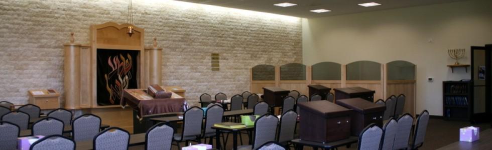
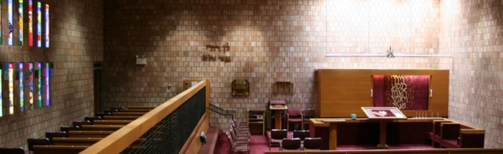
Figure 25. Young Israel of Southfield has all hard interior surfaces except pew upholstery and some carpet. The ceiling is at optimum height for both good sound distribution and control of reverberation for clarity. Rossen-Newman Architects, KMK acoustical consultants. Photos from website.
The problem does exist for a central reading desk, leaving some congregants behind the Cantor and others chanting at that desk. The chanting can be followed in prayerbooks and Hebrew Scriptures available to all worshippers, mitigating the problem. The “drash” or homily or sermon takes place with the front wall behind the rabbi, who faces the congregation. A state-of-the-art acoustical design that does try to maximize intelligibility is suggested in Figure 26.

Figure 26. An acoustical state-of-the-art synagogue. Again, the ceiling is at optimum height for both good sound distribution and control of reverberation for clarity. In addition, canopy over the “drash” location provides early reinforcement of direct sound, and the diffuse ceiling over the central reading desk on the “Bimah,” provides high-frequency reinforcement for listeners behind the back of the person chanting.
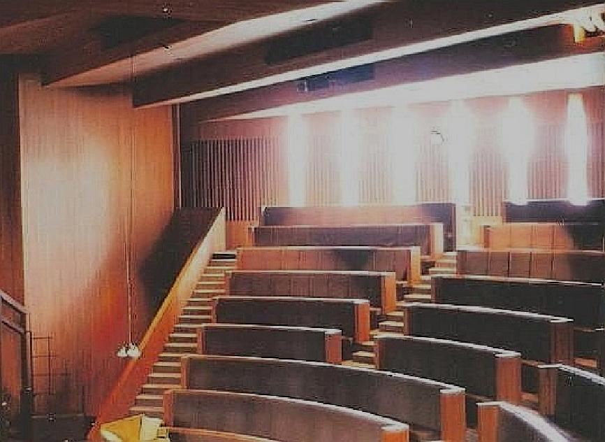
Figure 27. The Theater at Christian Theological Seminary, Indianapolis, a three-quarter-round space, proved the design concept suggested for the state-of the art synagogue. Edward Larrabee Barnes architect, and KMK acoustical consultants.32
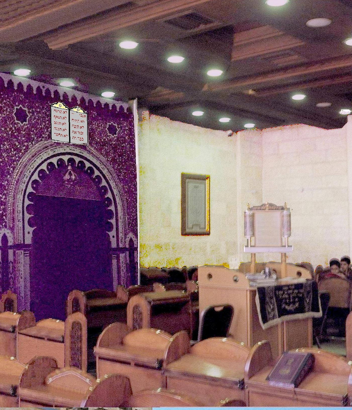
Figure 28. The Benyamin Lamar Synagogue, Jerusalem, is a realization of the state-of-the-art design, except for the “drash” canopy. The excellent acoustics are a compliment to services in the North African tradition, with each service a musical treat.
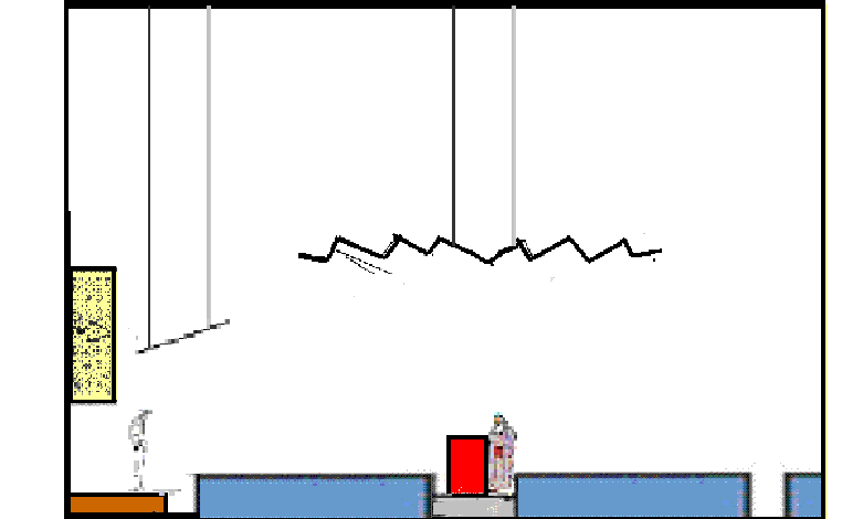
Figure 29. An answer to a friend who requested help with regard to a high-ceiling synagogue design.
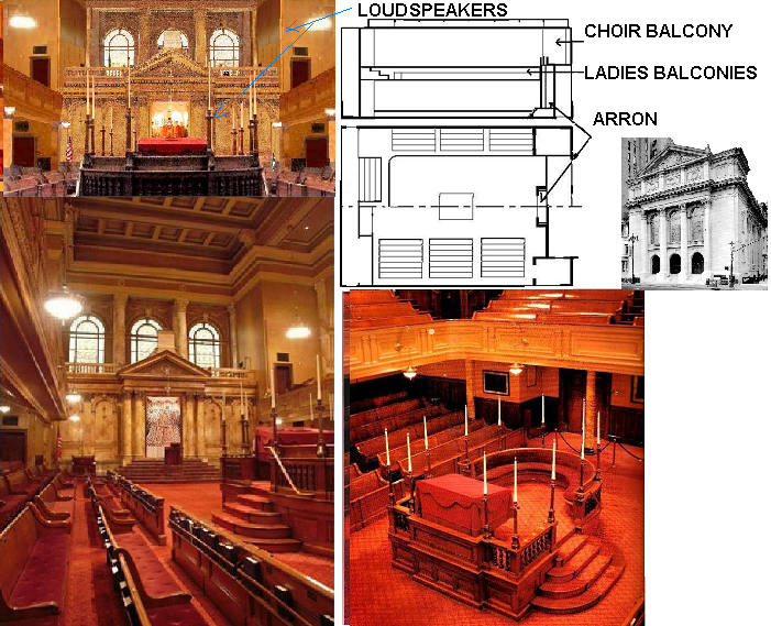
Figure 30. New York City’s Congregation Shearith Israel, the Spanish and Portuguese Synagogue, North America’s oldest congregation (1654) in its fifth building (1897), the first synagogue with a sound system following Zomet principles for Shabbat use,31 for increased Clarity in a 1.7-second reverberation-time room. The author believes that the architect, Arnold Brunner, looked to Mechanics Hall, Worcester, Massachusetts, for both basic design and details.33 However, Louis Comfort Tiffany is credited with the details of the interior, including the stained-glass windows. Dan Clayton’s update uses four computer-steered-array line-source loudspeakers, replacing a four simple-line-source pioneer system, by Arnie Goldfarb assisted by the author.34 CDs available.
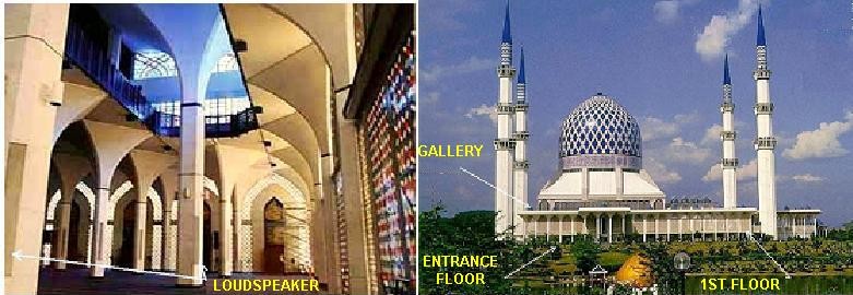
Figure 31. The Sultan Salahuddin Abdul Aziz Shah Mosque, Shah Alam, Malaysia, has the largest dome of any religious building. It also has the most complex and largest sound reinforcement system, using the directional properties of loudspeaker systems to control echo and reverberation, rather than the use of sound-absorbing treatment.35
The Sultan Salahuddin Abdul Aziz Shah Mosque, Shah Alam, Malaysia, is an example of providing intelligibility by a sound system that increases clarity as well as loudness, while not adding sound-absorbing treatment. 22,000 worshippers can be accommodated at one time. Calculated reverberation time is between 7 and 9 seconds.
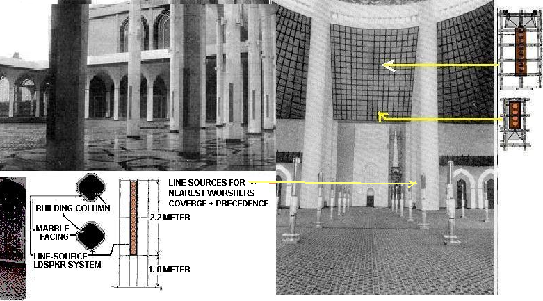
Figure 32. The Mosque’s overall sound system uses two large central clusters with 15″ bass direct radiators in line-source formation and mid-and-high-frequency constant-directivity horns to cover the main praying area under the dome, one for near and one for middle and far worshippers. Many line-source loudspeakers are built into building columns under and above balconies (galleries) and in courtyards. The full length of sixteen loudspeakers is driven below 2500 Hz, and only the bottom half in the treble range. Hundreds of ceiling distributed loudspeakers are used in supporting spaces, some capable of being used as independent systems as well as supplementing the main system for overflow and monitoring. Digital delay is used where desirable for synchronization. Larry Philbrick was the system designer (BBN, now Acentech). He and I both hope some day a thorough, documented acoustical analysis can be funded, but meanwhile, the system provides the needed intelligibility.
The main spaces of the mosque are built on a platform one level above ground level (Figure 31) and include the Grand Prayer Hall and four large courtyards connected by colonnaded verandas and galleries. The prayer hall (Figure 32) covers an area of 75,000 square feet, and is surrounded by a dome rising 250 feet above the floor. A gallery for women surrounds the perimeter of the prayer hall. The courtyards and verandas cover an area of 180,000 square feet. (From R. L. Philbrick, Ref. 35.).
Mt. Zion Sephardic Synagogue
This is the synagogue I usually attend on Shabbat mornings when not praying at my Yeshiva. It is located just outside the Old City near Zion Gate. I first attended in 1966, before Jerusalem’s Unification. 1948-1968, it was the closest to the Temple Mount, the Western Wall, and the Old City Jewish Quarter where an Israeli Jew could pray, and it was packed with standees every Shabbat. The Hazzan (Cantor) was and still is Rabbi Avraham Caspi, who is a renowned authority on Sephardic music, and so the liturgy is beautifully sung with many in the congregation having opera-star voices, and some were also regular attendees in 1965. The tiny synagogue is still packed on the Shabbatot between Passover and Shavuot, when Pirkey Avot, The Sayings of the Fathers, is sung with special melodies.36
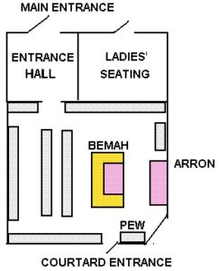
Figure 33. The design of the Mt. Zion Sephardic Synagogue is more typical of the small Hassidic and Ashkenazi Shtiebela (Yiddish for small rooms)37 that are also tiny and accommodate large congregations by having multiple praying times for each service every day. (Most Sephardic synagogues are larger and have the women’s praying area in a balcony, often U-shaped, as in Figure 30, or at the rear or main-floor-rear, synagogue of Figure 29.) All surfaces are hard, and the room is small enough so nearly all sound is early. An excellent six-CD set, “A Song of Dawn,” Shiray HaBaqqashot, (Songs of Beseeching), is available from the Musicology Department of the Hebrew University, at the National Library on the Ramat Gan, Jerusalem, campus. Contact Talischach@gmail.com.
Acknowledgments
I thank Allan Pierce, Doug Kleeger; and Marshall Long, who read drafts and pointed out errors. Harold Marshall pointed out style errors. Also, of course, the students and teachers at my Yeshiva for their tolerance.
References and Notes
1D. Malon and E. Wood, Sound Ideas, Acentech, Cambridge, MA, 2005, p. 62, 63, 76, 144, 186, 296, 332. My employment with BBN started 1 May 1957, not 1958.
2D.L Klepper, “Sound Systems in Reverberant Rooms for Worship,” Journal of the Audio Engineering Society (JAES), Aug. 1970, also in Sound Reinforcement, AES Anthology, New York, 1978, p. E-46-E56; M. Kleiner, D. L. Klepper, and R. Torres, Worship Space Acoustics, J. Ross, Fort Lauderdale, 2010.
3P. H. Parkin and J. H. Taylor, ,,Speech reinforcement in St. Paul,s Cathedral,,, Wireless World 58:2, 58-61 and 58:3, 109-101 (1952), and reprinted in the JAES, 54, p. 67-74 (2006)
4Some may still only consider reverberation time: D. Allcott, “Faith comes from Hearing,” Sound and Communications (S&C), Jan. 2012: The acoustics were judged in an all-hard empty church, and sound absorption was installed, possibly in greater quantity than the very best sound system would have required. Compare with A. Vargass, “With the Right Tools,” S&C., April 2015, p.22, 24-25, 102-103. The latter approach is the one I prefer, since the contractor in the second case devised an unusual sound system to meet existing room conditions. This approach will avoid provoking a conflict with the church musicians. Some manufacturers’ guides for contractors still suggest adding sound absorption as the first approach to intelligibility. And for some, faith can come from singing!
5M. D. Egan, Architectural Acoustics, McGraw-Hill. New York, NY 1988, p. 98.
6M. Long, Architectural Acoustics, Academic Press. New York, 2006, p. 671-674. Second Edition, 2013, p. 748-752. The definition of the term clarity factor as C80 is given on page 673 in the First Edition and p. 751 in the Second Edition. Speech intelligibility is addressed p. 590-604, First Edition and p. 648-663 in the Second Edition
7L. G. Marshall, “An acoustics measurement program for evaluating auditoriums based on the Early/Late Sound Energy Ratio,” J. Acoust. Soc. Amer., 96, 2251-2261 (1994); “An analysis procedure for room acoustics and sound amplification systems based on the Early/Late Sound Energy Ratio,” Journal of the Audio Engineering Society, (JAES) 44, 373-381 (1995), reprinted in Sound Reinforcement, 2, Audio Engineering Society, New York, 1996′ pp. 380-388.
8J. Eargle and C. Foreman, Audio Engineering for Sound Reinforcement, Hal Leonard and JBL Pro Audio Publications, 2002, Milwaukee, p. 218
9W, Reichardt,, A. Alim, and W. Schmidt, “Zusammenhang zwischen Klarheitsmass, C, und anderen objektiven raumakustischen Kriterien,” (Correspondence between the metric Clarity C and other objective criteria for room acoustics) Z. elektr. Inform, u. Energietchnik, Leipzig, 5, 144-155 (1975)
10M. Long, Architectural Acoustics, Academic Press. New York, 2006, p. 85-89. Second Edition, 2013, p. 96-98. Noise Criteria curves and their basis.
11W. R. Farrell, “Masking Noise Systems in Open and Closed Spaces,” JAES, (March, 1975), reprinted in Sound Reinforcement, AES Anthology, New York, 1978 p. E62-66.
12W. J. Cavanaugh, W. R. Farrell, P. W. Hirtle, and B. G. Watters, “Speech Privacy in Buildings,” J. Acoust. Soc. Amer., 34, 475-6 (1962).
13L. L. Beranek, “Sound Systems for Large Auditoriums,” J. Acoust. Soc. Amer., 26, 661-675 (1954).
14D. L. Klepper, “The Distributed Column Sound System at Holy Cross Cathedral, Boston, the Reconciliation of Speech and Music”, J. Acoust. Soc. Amer., 99:1, 417-425 (1996). The excellent 1875 Hook & Hastings organ in this Cathedral is discussed in B. Owen, The Organ in New England, The Sunbury, 1979, p.324-326, 600, 607, available from the Organ Historical Society, Richmond, VA,. But the organ is no longer neglected! (Again, CDs are available.)
15D. L. Klepper, “First Presbyterian Church, Stamford, Connecticut,” J. Acoust. Soc. Am. 31, p. 879–882, (1959). Years of hindsight suggests the words “early sound energy” should have been used instead of “direct sound” throughout this paper.
16D. L. Klepper, “Tent shaped concert halls, existing and future,” J. Acoust. Soc. Am. 124, p. 15–18, (2008).
17L. L. Beranek, Music Acoustics, and Architecture, Acoustical Society of America, New York, 1962, Chapter 6, p. 43 – 610. The music acoustics of Cloughs Hall was discussed in this book, but not included in the latter two Beranek concert hall books. Sound system details were not discussed. Other halls discussed in this book but not in the two later Beranek concert hall books, include Cambridge, Massachusetts, M. I. T., Kresge Auditorium; Calgary and Edmonton, Saskatchewan, Canada, Jubilee Halls; New York City, Metropolitan Museum, Grace Rainey Rogers Auditorium.
18C. R. Boner, “Some Examples of Sound-System Correction of Acoustically Difficult Rooms, JAES, (April, 1967), reprinted in Sound Reinforcement, AES Anthology, New York, 1978 p. B10-12. The first system discussed is an example. The others, for various reasons, used distributed loudspeaker systems.
19V. M. A. Peutz and W. Klein, “Articulation loss of consonants in the presence of noise, reverberation, and echo” (trans. from Dutch), Acous. Soc. of Netherlands 28, 1974; V. M. A, Peutz, “Articulation Loss of Consonants as a Criterion for Speech Transmission in a Room,” JAES, Dec. 1971, also Sound Reinforcement, AES. Anthology, New York, 1978, p. A23-27; W. Klein “Articulation Loss of Consonants as a Basis for the Design and Judgment of Sound Reinforcement Systems,” JAES, Dec. 1971, also Sound Reinforcement, AES Anthology, New York. 1978, p. A28-30 plus correction on p. A31.
20R. C. Heyser, “The Determination of Loudspeaker Signal Arrival Times,” JAES 19, Part 1, p. 734-743, Oct. 1971, Part 2, p. 829-834, Nov., Part 3, p. 902-905, Dec.; also Sound Reinforcement, AES Anthology 2, New York. 1996, p. 82-114.
21D. Davis and C. Davis, “The Application of Intelligibility to Sound Reinforcement,” JAES, 39, p. 1002-1019, (Dec. 1989), and Sound Reinforcement, AES Anthology 2, New York. 1996, p. 438-454.
22C. Curtis and C. R, Emerson, “Those Early Late Arrivals, Mr. Haas, What Would You Do?” JAES, 28, p. 40-45, (Jan.-Feb. 1980), and Sound Reinforcement, AES Anthology 2, New York. 1996, p. 400-409.
23J. P. A. Lochner and J. F. Burger, “The Influence of Reflections on Auditorium Acoustics,” Journal of Sound and Vibration, 1, p. 426- (1964).
24J. J. Figwer, “A New Method for Evaluating the Effectiveness of Sound Amp-lification Systems in Reverberant Spaces”, JAES, 16, Oct. 1968`p. 416-418, reprinted in Sound Reinforcement, AES Anthology, New York, NY (1978), p. A-13-15.
25D. L. Klepper, The Acoustics of St. Thomas Church Fifth Avenue.”, JAES 43:7/8, p. 99-101 (1995), also Sound Reinforcement 2, AES Anthology, New York, 1996, p. 392-394.
26D. Clayton and C. Whitney, 147th ASA Meeting, 75th Anniversary, Organ Recital (program). Acous. Soc. of Am, Melville, NY (2004)
27H. Haas, “Uber den einfluss eines ienfachechos auf die Horsamkeit`von sprache,” Acoustica 1, I1951) p. 49-58. English translation by K. P. R. Ehrenberg as “The influence of a Single Echo on the Audibility of Speech,” Building Research Station Library Communication 363, Dec. 1949, Watford, Harts, England, reprinted in JAES, 20, March 1972, and in Sound Reinforcement, AES Anthology, 1978, Audio Eng. Soc, N.Y., p. C-20.
28R. H. Bolt and P. E. Doak, “A Tentative Criterion for the Short-term Transient Response of Auditoria” J. Acoust. Soc. Amer., 22, p. 507-508, (1950)
29L. L. Beranek, Concert Halls and Opera Houses, Music Acoustics and Architecture, Academic Press., Springer-Verlag. New York, 2002, p. 513. Note that all acoustical terms and abbreviations used by this author are well-defined in this book, p. 25-39. It has an excellent index and a comprehensive reference list. Available from the Acoustical Society of America. Note should be taken of the comment by M. Barron on pages 671 and 672, First Edition, of the M. Long book, Ref. 6 and 10.. In this book p. 654 and 655, First Edition, give definitions of musical and acoustical terms. This book also has an excellent reference list and index.
30P. Mapp, “Measuring Intelligibility,” S&C, April 2002, p. 56-68. Note also his discussion of specific equipment problems, S&C, April 2015, p. 12, 14. My own equipment recommendations follow along another of my contributions to this web encyclopedia, although a good used Crown Techron TEF-20 at the right price can be a good substitute for the best new equipment. I suggest reading all Peter Mapp’s S&C monthly columns.
31D. L. Klepper, “A Different Angle,” Sound and Video Contractor, January, 1999; and Rabbi Yisroel Rosen and E. Rosenfeld and others, Crossroads, Halacha and the Modern World, Zomet Institute, AlonShvut, Gush Etzion, Israel, 1988-1999, Vol. 2, p. 18-25, Vol. 4, p. 7-13, Vol 5. p. 10-41.
32D. L. Klepper, “Behind the Actor’s Back,” JAES. July 1955 and Sound Reinforcement, AES Anthology, 1978, p. E-19-21, for design principles.
33W. J. Cavanaugh and D.Kaye, “Preserving the acoustics of Mechanics Hall: A restoration without compromising acoustical integrity,” Technology and Conservation, Autumn 1980. Also Beranek as in reference 29, p. 153-160.
34M. Kleiner, D. L. Klepper, and R. Torres, Worship Space Acoustics, J. Ross, Fort Lauderdale, 2010, p. 287-289, for discussion of the congregation, its music, and the building. For a complete history of this congregation, and its importance to the USA and the Jewish People, see M. D. Angel, Remnant of Israel, Riverside, New York, 2004, available from the congregation. This congregation upholds the highest standards of quality in everything they do: music, educational opportunities for young and old, visual beauty, and food at congregational meals. Music and speech and music CDs available, www.shearithisrael.org
35R. L. Philbrick, “Tbe Sound System for Shah Alam Mosque,” presented at the Sixth AES International Conference, 1988. See top Reference 34, Chapter 13, p.257-269 for general information on Mosque acoustics and Islam, with notes and further references p.294-295. Recommended is a visit to New York City’s Islamic Center at East 96th Street and Third Avenue, where visitors are welcome in this beautiful building during Friday prayers. Shoes must be removed before entering the hall of prayer, women have their own location, and visitors are expected to move their bodies in conformance with the rest of the congregation.
36The site of this synagogue is thought by most experts to be the site of Jesus’ Last Supper. Thus, the Roman Catholic Church has a claim in for ownership. Ehud Olmert was willing to transfer ownership when he was Prime Minister, but was opposed on both religious and patriotic grounds, given the history of the congregation. A rational approach would be to give any Israeli church, any denomination, the right to visit by a prior arrangement with a member of the regular congregation acting as tour guide and guard. Such an arrangement may be in effect informally at the present time. I would like to see this right extended to any educational institution that teaches tolerance across religious boundaries and to all such institutions in the neighboring countries and those under the control of the Palestinian Authority. Overseas churches would make arrangements through local churches. I have observed Christians praying silently in the Hebrew University’s Hecht Synagogue and at the reputed tomb of King David. A nun dressed in white with a tiny gold cross prayed with the women at the Mt. Zion for about a year. The Psalms and much else are common to both religions. Not all songs in the “A Song of Dawn” CD set were recorded in the synagogue. Many were recorded in the adjacent large and more reverberant room between the synagogue and reputed tomb of David, and the Hebrew University CDs preserve the acoustical differences. My own voice was part of the chorus during many songs, but not all the time, and thus I, like others, am not included in the list of singers.
37Top reference 34, p. 215-216. There were two Shtibela as described in this reference in my current apartment building, both on the ground floor, one next to my apartment. The congregation at the end of the building, next to the building’s convenience store, has moved to larger quarters nearby, in a building that will be very beautiful when finished.
About the Author
David Lloyd Klepper is currently a student of Rabbinics at Yeshivat Beit Orot, Jerusalem, Israel, having moved to Israel in 1996 from his position as President of Klepper Marshall King, White Plains, NY, Acoustical Consultants, and as Adjunct Professor of Architectural Acoustics at City University, New York City. Before 1971 he was a senior consultant at Bolt Beranek and Newman, starting his consulting career there in May 1957. He received his SM and SB degrees in Electrical Engineering from MIT, and between times served as Assistant Audio-Radio Member of the PsyWar Board at Fort Bragg, NC, during the Korean conflict, leaving active duty as a 1st Lt. He provided acoustical advice for over 200 worship space buildings, including the National Presbyterian Church, Washington, DC, St. Thomas Church Fifth Avenue, New York City, the Capetown, South Africa, Anglican Cathedral, River Road Baptist Church, Richmond, Virginia, Young Israel of Southfield, Michigan, and Boston’s Holy Cross Cathedral. In this capacity, he was a pioneer in application of digital delay and electronic simulation of reverberation in worship spaces, and pew-back speech reinforcement. Publications include 40 papers in professional journals, a coauthor with Professor Kleiner and Father Rendell Torris of the book Worship Space Acoustics, JRosspub.com., and Editor of the two Sound Reinforcement Anthologies of the Audio Engineering Society. He is a fellow of both the Acoustical Society of America and the Audio Engineering Society, past Emeritus Board Certified member of the Institute of Noise Control Engineering, and a member of both the American Guild of Organists and the Organ Historical Society. He also belongs to a number of railroad and public transit interest organizations. You may contact Klepper at ddaveklepper1@gmail.com.
Editor’s Note
A companion paper entitled, “The Early-To-Reverberant Sound-Energy Ratio In Concert Hall Acoustics”, by David Klepper, may be found here.