Originally posted in the April 1977 issue of Recording Engineer/Producer (RE/P). Abadon/Sun Studio was located in San Antonio, TX.
By Woody Smith & Galen Carol
We at Abadon/Sun decided to write this article because we felt a large number of small studio owners required more information to properly design and build their first studio. What we’ve tried to do is to simplify things as much as possible and provide the builder with the design fundamentals.
Since most small control rooms are rectangular in shape we’ll detail the design considerations for a room of that shape. Our primary goal is to eliminate severe resonant modes in the room and establish the low-frequency response of the room through the proper selection of room dimensions.
RESONANT FREQUENCIES
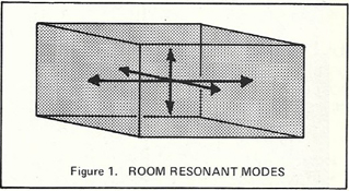
A room with parallel surfaces and no acoustic treatment will exhibit resonant modes between ‘Opposite surfaces. That is, we will have resonances created between the two side walls, the front and rear walls and the floor and ceiling surfaces.
When selecting the various room dimensions the objective is to avoid common resonances between any of the room modes to avoid build-up of sound at the resonant frequencies (Figure 1). If a common resonance is present, it will probably result in an increase in volume of that one frequency producing a very boomy sound (for low-frequency resonances). Since the low frequencies are the main source of difficulty in room design (and are the hardest to correct) this article will concentrate on them.
The frequencies at which resonance occurs are determined by the distance between the two walls under consideration. The formula for the resonant frequencies is:
![]()
where d is the room dimension (in feet) and fn is the resonant frequency (in Hz. or cycles/second). The resonances will occur at multiples of the fundamental frequency f(I). For that reason we use the multiplier (n). For example, two walls separated by 10 feet will produce resonances at 56.5 Hz., 113.0 Hz., 169.5 Hz., etc. By this method the resonances occurring in the room can be readily calculated. Considering a room 10′ x 15′ x 20′:
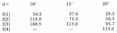
Our conclusion from these calculations is that 10′ x 15′ x 20′ is a very bad choice of room dimensions. The reason is that we have a resonant frequency (113 Hz.) common to all three room dimensions. This would produce a very bad room resonance every time we encountered a 113 Hz. signal which would probably occur fairly frequently.
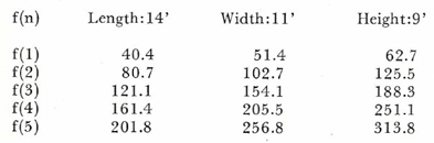
Changing our choice of dimensions to 10′ x 14′ x 22′ and applying the same equations we find these resonant frequencies:
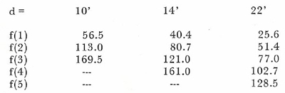
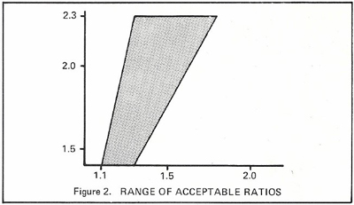
As can be seen there is no common resonant point between the dimensions selected this time. One limitation we will impose on your choice of room dimensions is that the ratio of dimensions should lie within the limits of the graph given in Figure 2. For example, a room measuring 10′ x 11′ x 18′ would have a ratio of dimensions of 1: 1.1: 1.8 which would not be acceptable. A room with dimension ratio of 1:1.4:2.2 is within the acceptable range.
[NOTE: Some of the ratios within the limits of the graph may produce undesirable additive resonances. For this reason you must check them thoroughly by calculating the resonant frequencies before committing yourself to a selection.]
Another calculation which will enter into your choice for dimensions is the diagonal dimension of the room. For a room to reproduce low-frequencies well, there has to be a sufficiently long dimension to allow the low frequency waves to propagate themselves. The equations are:
![]()
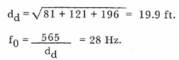
The room diagonal can be found from the equation:
![]()
From these equations you should be able to determine the lowest frequency that can be propagated in the room. The diagonal lengths required for some sample frequencies to propagate are given as:
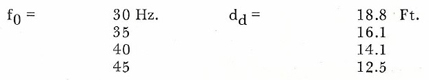
Looking at another example, a room 9′ x 11′ x 14′ is suggested. The ratio of dimensions is 1: 1.2: 1.6 which is acceptable according to our graph of acceptable ratios. The lowest frequency will be:
Room resonant frequencies are:
From these calculations we can see that this is an acceptable choice of dimensions.
CONSTRUCTION DETAILS
Once the room dimensions have been selected we can begin looking into the finishing of the walls, ceiling and floor. Sound travels by both acoustic and mechanical means. That is, it not only travels through the air but also through solid objects. So, to minimize the leakage of sound between rooms we must provide both acoustic and mechanical isolation.
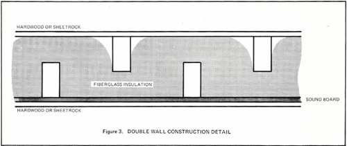
Maximum mechanical isolation is best achieved when the inner and outer walls are independent; as in the use of doublewall construction. This type of construction uses separate, staggered studs for the inner and outer wall surfaces with fiberglass insulation in between (Figure 3). Also, care should be taken to insure that no holes exist between the two rooms, such as through adjacent electrical outlets or mic lines run through the walls, since an air-tight seal between the rooms is required for maximum isolation from air-borne sound.
Walls other than those between the studio and control room may be of single-wall construction but should be packed with insulation.
As to wall surfaces, the heavier a wall covering is, the lower its’ resonant frequency. Normally we’ll want the resonant frequency to be as low as possible. Sheetrock will resonate at a lower frequency than thin paneling because of its increased weight. We can also reduce sound transmission and lower the resonant frequency of a wall by the use of a highly damped material such as sound attenuation board. For example, by attaching thin wood paneling to sound attenuation board added weight and thus, damping will be achieved. This provides the twin advantages of an attractive surface that exhibits good acoustic characteristics. Typically, windows should be of double-pane construction with the two panes at angles to each other to eliminate internal resonances. All seals around the window should, of course, be air-tight (Figure 4).
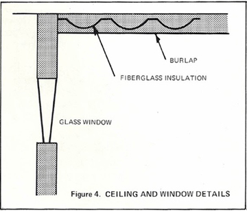
Experiments have led to the belief that the ceiling should be padded with 4″ thick fiberglass insulation folded slightly to produce a corrugated surface. This should then be covered with burlap or other similar material. The effect is to deaden the ceiling and reduce floor-to-ceiling resonances. To retain a proper stereo image in the control room the need to have a room symmetric about its center (front to rear) axis has been well proven. That is, the side walls should be mirror images of each other. If they are not, the acoustic characteristics of the two walls may be different.
Let’s say one wall has a hard flat surface and the other wall is made very dead. The hard surfaced wall would produce lots of reflections back to the console making that side seem both bright and loud. The deadened wall would do just the opposite by absorbing the sound hitting it, resulting in a dull sound at reduced level. It’s obvious from this that the hard surfaced wall and the dead wall both have shortcomings. We prefer to use side walls which are irregular in shape and texture to minimize resonances between the two walls and also to break up any reflections from the walls. We will try to avoid using deadening materials on the two walls because we do want them to retain a bright sound.
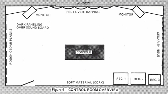
This type of side wall construction can be seen in Figure 4, for which we’ve used cedar shingles to form a pattern on the wall. The wall also has a slight curvature to it to further reduce resonances between the two side walls. The surface formed by the shingles is acoustically hard but very irregular so that reflections produced by the wall are diffused. This will further enhance the stereo image produced by the monitors through de-centralization
of the sound source.
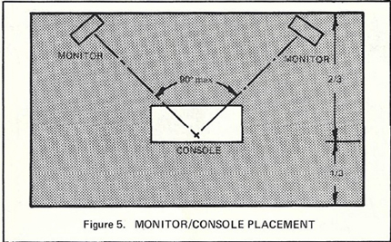
An additional prerequisite for proper design is that the console must be centered between the walls, and the monitors should be placed at equal distances from the side walls. The criteria for monitor placement has been outlined in Figure 5. From your position while mixing, the angle between the monitors shouldn’t exceed 900 and their axes should cross about one foot in front of you. If possible you should be about two-thirds of the distance back from the monitors to the rear wall.
The choice of monitor loudspeakers is practically unlimited. The monitors ultimately selected should be as reliable as possible and be capable of high sound pressure levels. The reasoning behind this is that in mastering use a monitor is fed a fairly high continuous level of uncompressed sound. Allowing 10 dB of headroom for peaks in the music, a 95 dB SPL signal may reach 105 dB SPL on transients. This is not very dramatic to the ear, but is a drastic change to the speaker. 10 dB translates to ten times power, so if we were using 20 watts continuous power for 95 dB SPL, the speakers would require 200 watts peak input for 105 dB SPL.
A speaker requiring only 8 watts for the same 95 dB SPL would require 80 watts peak. It is advisable to allow at least 10 dB above your continuous monitor level for peaks and you should select a monitor capable of handling repeated inputs at 10 dB above that level without failure or distortion. Obviously, the power amplifier should be chosen after you choose the speaker unless you plan on buying a big amplifier. We normally install Crown D-150As with JBL 4311 (monitors) or Klipsch monitors, and Crown DC-300As with everything else.
Placement of the monitor speaker in a corner of the room will reinforce the bass output of the monitor as will placing it near the floor or ceiling of the room. Placement in the center of a wall will provide the least amount of reinforcement. If you want to demonstrate this effect simply place a speaker on the floor, run pink noise (or FM inter-station noise) through the speaker and slowly lift it off the floor. You will notice a marked change in the sound of the speaker.
We recommend that you allow some time to tryout several different monitor placements in your control room before committing to a certain spot. However, the relationship between monitor and console placement as outlined in Figure 5 should still apply regardless of your final choice for the monitor placement.
At Abadon/Sun we consider several things to be important in the early stages of design concerning the aesthetics of the control room. We center our designs on providing the mixing engineer a comfortable place to work. This includes providing comfortable surroundings and eliminating unnecessary distractions. For that reason we like to place all the recorders and accessories behind the mixer, or to his side so that when he is mixing there are just the artists performing and the console readily visible to him. This excludes, of course, such things as limiters which must be adjacent to the console but should be below eye level.
Proper lighting of the control room is also important. We normally light the area of the console with multiple low intensity flood lights on overhead tracks and soft light the recorders with additional track lighting. This eliminates quite a bit of the distraction that arises from all the moving meters and lights on equipment other than the console.
The point behind all this is that the mixing engineer’s attention is concentrated on the work at hand which in turn leads to a better product. As a further extension of the same ideas, we recommend the use of dark colors and wood surfaces in the control room. For example, try using sections of dark walnut paneling and sections of padded felt in dark blue or black. The effect is very pleasing.
You should now have all the basics required to construct a good control room without a lot of guesswork. The 9′ x 11′ x 14′ room discussed earlier has been recently built and seems to work very well. Please remember that it is based on a small control room situation and as such is merely one design approach, however, it is a proven approach which provides excellent results in a minimum of space.