Editor’s Note
This is an important piece of audio history presented by noted acoustical consultant David Klepper. In this article, Klepper offers basic design theory for columnar line-source loudspeakers (line arrays) and relates his own part in the early development and application of this product type, now offered in several forms by a variety of manufacturers and commonly used in both installed and portable applications.
A Personal History with Line-Source (Column) Loudspeakers
Introduction by the Author
After the Second World War, sound system designers took either of two design approaches for speech intelligibility and music reinforcement in large spaces, either efficient directional horn loudspeakers, most frequently multicellular, or column or line-source loudspeakers made from a number of identical paper-cone-type loudspeakers in a vertical or near-vertical line array. Accounts of the application of directional horn loudspeakers, one as long as 63 years ago, are on this website.1, 2 Some of those reports show applications of line-source (column) loudspeakers, but only two from such an early period. Although I have discussed this type of loudspeaker previously,3,4,5 my recounting more fully contact with use of this type of loudspeaker system may provide some more useful non-technical bit of history. A bit of organ history is also included.
David Lloyd Klepper
Yeshivat Beit Orot, Shmuel ben Adiya 1, Mt. of Olives, Jerusalem 97400, Israel. daveklepper@yahoo.com
Early Applications and Theory
Early sound reinforcement systems used efficient horn loudspeakers as soon as they were available, and the directional characteristics of the horns, as well as the relatively high electrical-to-acoustic energy conversion got practical results from the relatively low power of triode output-tube amplifiers giving rarely more than twenty watts while barely fitting in an automobile trunk. With multi-grid output tubes and more powerful amplifiers available after WWII, efforts began to explore providing sufficiently loud amplification and directional control. The idea of a line of loudspeakers concentrating energy in the on-axis direction with in-phase energy addition, while reducing energy elsewhere, because of more random phase of arriving energy, and with power amplifiers powerful enough to adequately power all the direct radiator cone loudspeakers in the column, was a natural development. The theory is discussed in the 1952 paper discussing the pioneering installation in St. Paul’s Cathedral, London.6
Commercial applications in North America were pioneered by North American Philips, with cone loudspeakers manufactured in Holland. Arnold Goldfarb directed this pioneering effort, and an early application was the system he installed at New York City’s Congregation Shearith Israel. Some thirty years later, this system was modified to become the first to receive Sephardic Rabbinical authorization for use on Sabbaths, with Arnie Goldfarb following Israel’s Zomet’s guidelines under Israel’s Chief Sephardic Rabbi.
The simple line-source idea was soon implemented by North American manufacturers and contractors, Locally produced loudspeakers were less expensive, and eventually, Philips left this portion of their North American business.
Considering the vertical line of loudspeakers a series of point sources, the applicable equation for variation of sound level off-axis vertically far from the loudspeaker system is Eq. 1:
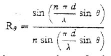
Equation 1 (See Reference 6)
R is the absolute (not decibel) ratio of the sound level at the angle off the axis to the level on-axis, n is the number of loudspeakers, and d is the distance between them, with (n-1)d being the total length of the line. is the wavelength of the sound energy.
If we replace the series of point sources with a continuous line, constant energy radiated along its length, the equation is Equation 2 (where l is the length of the line):
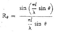
Equation 2 (See Reference 6)
If radiated energy is evenly tapered, center of the line to zero at its end-points, the equation is Equation 3:
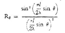
Equation 3 (See Reference 6)
Figure 1 a & b
Polar plots: a. 11 ft., 1K Hz, continuous (solid) and tapered (dashed)line.6 b. St. Paul’s, eleven 10-inch bass loudspeakers, nine 3.5-inch treble loudspeakers, crossover 1000 Hz,, solid curve 1000 Hz for bass, 4000 Hz for treble, dashed 250 Hz bass, 1000 Hz treble;6 c. Section showing construction to reduce side lobes;6 d. photo of St. Paul’s line-source,6 e. Photo of smaller St. Paul’s line-source as used multiple times on Nave columns.6 f. Loudspeakers for L. L. Beranek’s 1952 test installation at Boston’s Holy Cross Cathedral.7 g. Bozak and NEAR 888 line-source loudspeaker, as in 1966 New York City Parks Concerts, 1976 Stephen Wise Free Synagogue speech reinforcement, and 1986 Boston Holy Cross Cathedral speech and ethnic music reinforcement.8
Polar plot “a” in Figure 1 shows the directional characteristics of an 11-foot line at 1000 Hz for both the continuous and the tapered cases. Examination of both equations 2 and 3 show that if l/is held constant, the directional characteristics will be unchanged. Thus, polar plot “a” remains the same for a 22-foot line at 500 Hz, or a 5.5-foot line at 2000 Hz, or a 2.75-foot line at 4000 Hz. A real-life line-source (column) loudspeaker is neither purely a series of point sources, nor a continuous line, but the theory of the ratio of wavelength to line-length governing the directional characteristics holds, and Polar plot b shows it applied to the main London St. Paul’s Cathedral loudspeaker systems, as discussed in the 1952 Wireless World paper.6
In an effort to control side-lobes (up-to-the-ceiling and down-to-the-floor), the rear of the main loudspeaker enclosures were not closed with hard wood but with porous sound-absorbing material, as shown in Figure 1-c. Figure 1-d gives the idea of the scale of these loudspeakers systems.
Boston, Holy Cross Cathedral 1954 Experimental System
The success of the St. Paul’s. London, system spurred the experimental system at Boston’s Holy Cross Cathedral, using the column loudspeakers illustrated in Figure 1-g. The loudspeaker layout can be seen in in Reference 1-a on this website and in Beranek’s 1994 paper, Reference 7, and with the St. Paul’s loudspeaker layout in my 1996 paper, Reference 8. Shortening the line was done with one step at St. Paul’s by the high-frequency loudspeakers forming a much shorter vertical line than the bass loudspeakers, but this was not done in Beranek’s Boston experiment. However, some broadening of the coverage resulted from tapering the line output as seen in the circuit diagram with resistors in the feed to the outer loudspeakers.
The loss of directivity at higher frequencies, seen the 1-g frequency response curves, would appear to contradict the line-source theory discussed above. There are two reasons why high-frequency energy from these particular loudspeakers may not have been exactly in phase, thus more approximating a random collection of loudspeakers than a close approximation of a line source at high frequencies. First, these Stromberg 4-inch loudspeakers were not absolutely identical, as discussed in Reference 7, and because of random paper-cone variations, most irregularity occurs with increasing frequency, Second, a loudspeaker is not a purely resistive load, and adding a resistor in series is certain to produce some phase-shift, with the inductive component’s effect increasing with frequency. But this experiment was my first exposure to column loudspeaker technology.
A permanent installation in 1988, based on the Beranek 1954 experiment, used NEAR (formerly Bozak) 888 loudspeakers shown in Figure 1-h, modified for a downward tilt. The low-frequency loudspeakers of this loudspeaker system are all fed the same signal, but tapering is employed in the high-frequency section.
M. I.T. Acoustics Laboratories Line-Source
The winter of 1956-’57 and following spring to 1 May (when I joined the staff of Bolt Beranek and Newman), I was a research assistant at the M. I. T.’s Acoustics Laboratory, whose director was William Kessler. Gabe Farrell was the full-time researcher, and I assisted him in assembling and testing a line source (column) loudspeaker system of eight Western Electric 755A eight-inch loudspeakers, 12-inches on centers. (Manufacture of this loudspeaker was transferred from Western Electric to Altec Lansing, but the purchase by M. I. T. probably occurred before this change. The laboratory had a large stock of these loudspeakers, used routinely for many experiments.) At more than one demonstration of this system, the talker stood five or six feet directly in front of the floor-standing loudspeaker, and communicated to listeners some 150 feet (approx. 45 meters) away with the microphone four inches (0.1 meter) from his face, without feedback or ringing.
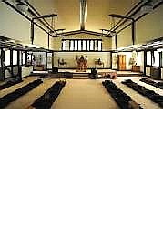
Application at Harvard’s Memorial Church
A year later, Bolt Beranek and Newman was contacted to improve the acoustics of Harvard’s Memorial Church. I was given responsibility for overall acoustics improvement for both speech and music and, somewhat later, Ted Schultz, a professional bassoonist with long-standing ties to Boston musicians, for organ-sound distribution improvement. On the basis of my recommendation, a thick Latex-based paint was applied, with multiple coats, to the sound-absorbing acoustic-plaster ceiling to render it sound-reflecting, and a simple sound system, using four column loudspeakers, similar to Gabe Farrell’s M. I. T. test loudspeaker, but with on-center spacing reduced to nine inches and employing only five loudspeakers, both to allow the line-source to fit space available and to make the line-source more continuous for and wider vertical coverage for this application. Figure 2 Illustrates how the system was employed.1d, 5 The forward tilt of each of the two Nave line-sources brought the maximum energy from them to the under-balcony seating area, and, indeed, speech intelligibility throughout all pew areas was excellent. The loudspeakers were completely hidden, the reinforcement natural sounding, with a responsible student controlling gain at a front-of-balcony control location.1d,5 This installation was Bolt Beranek and Newman’s first project using column – line-source loudspeakers. The Altec-manufactured 755A loudspeakers matched the performance of those from Western Electric, and I still regard them as the very best eight-inch cone-type loudspeakers ever made. They were also used at the Esso meeting discussed in Reference 1’s Frequency Shifter paper.
Organ and Choir Digression
Although Ted Schultz had the responsibility, at Bolt Beranek and Newman, for working with Charles Fisk on organ matters, my comments may be of interest. The organ from pre-WWII times was an Aeolian-Skinner, located in chambers on each side of the Appleton Chapel area, hidden from the Nave by location, by grills on the openings to the two chambers, and by the reasonably-sound-transparent rude-screen behind the lectern and pulpit, that continues today to separate the Chapel from the Nave. The choir, also behind the rude-screen, at least had line-of-sight through the screen to the worshippers in the Nave, although visually hidden. Thus, the balance between organ and choir was very different depending on where one sat in the Nave and/or balcony. On the basis of Ted’s recommendation, the then new Fisk organ was located to block the Chapel’s end window and face directly to the rude-screen and the congregation, see Figure 2. Harvard got a landmark in organ building, the very first American-made four-manual tracker-action organ. (Tracker-action: the historic practices of mechanically connecting each key to the valves permitting air to enter the pipes for that note, as in Bach’s day).
Problems of balance and communication were solved with regard to acoustics. They were not solved for sight-lines, because the choir was still separated from the congregation and did not have visual contact with the minister when he or she delivered a sermon. In retrospect, closed-circuit TV should have been provided. Possibly not recognizing this requirement was my failure?
Figure 2
The 1958 column loudspeaker system at Harvard University’s Memorial Church and the Ted Schultz located Charles B. Fisk four-manual tracker organ
After I moved to Israel in 1996, the landmark four-manual C. B. Fisk was sold to a Texas church and replaced by a new three-manual Fisk tracker-action organ at the rear of the balcony.9 I alerted Fisk’s people to a possible problem for choir and organ sound for worshippers in the under-balcony pews, but this worry was unnecessary. For the tracker-action to work, the organ case essentially has no floor, and the many vertical rods need to pass through the opening in the balcony floor to the space between the stepped balcony floor and the soffit (under-balcony ceiling) below, where horizontal rods connect them to the vertical rods connected to the organ console’s keys. This provides a path for organ and choir sound to reach the large return-air grilles in the soffit and thus to the congregants below. I was assured that Charles Fisk always wished to place the organ in the rear balcony. This is understandable because he had been a member of this church’s choir while a Harvard student and thus experienced the isolation the choir must have felt with their location in Appleton Chapel.
But, with the organ and choir now in the balcony, weekday small services in the Chapel were then without an organ. So, now a recycled Ernest Skinner organ has been installed in the old organ chambers with its own console in the Chapel for the Skinner organ’s electro-pneumatic action.
The 1958 ceiling treatment took the Nave from “hopelessly dead” to simply “dry.” With the ratio of seating area to room volume unchanged, it lacks the reverberation optimum for organ and choir sound, just good “lecture-hall” acoustics. A major step in resolving this problem for organ sound is possible by making the Chapel Ernest M. Skinner organ playable from the Fisk’s balcony console. This could be accomplished without modifying the console itself by electrical contacts on the back-falls in the plenum space under the balcony floor. Each Fisk stop6 would be paired with an appropriate Skinner stop. One “On-Off” switch should be sufficient.
Time was no kinder to my first line-source loudspeaker project than it was to Ted Schultz’s organ relocation! After I left the Boston area, a contractor called on to do repairs on the sound system thought the forward tilt of the loudspeakers was a mistake and left them aimed at the rear wall. Subsequent loss of intelligibility under the balcony led to the expense of under-balcony loudspeakers, hopefully with the necessary delay to match sound to that coming from the lectern and pulpit and front loudspeakers. There is currently a visually obvious sound system. Hopefully, the exposed column loudspeaker systems are of the state-of-the-art. computer-controlled type, and intelligibility is even better than from the 1957 system. I wonder where those fine 755A’s are.
New York City Parks Concerts
With Christophe Jaffe as acoustical consultant, the summer of 1966 saw the use of a Fiberglass-reinforced plastic orchestral enclosure flanked by two Bozak 888 two-way column loudspeakers, loudspeakers illustrated in Figure 1-h. Results were more than satisfactory for the New York Philharmonic’s outdoor orchestral concerts and Metropolitan Opera presentations of opera in concert form. But audiences grew, and listeners most distant had difficulty hearing. In 1976, the Jaffe enclosure and sound system was replaced by a Wenger demountable heavy damped steel enclosure with good bass response, flanked by two towers containing efficient James B. Lansing directional horn loudspeakers with complimentary horn bass enclosures with 15-inch bass loudspeakers. This was a Klepper Marshall King project, with the sound system installation by Rosner Custom Sound. At the same time, microphone arrangements were improved, and a more modern control console, with straight-line attenuators replacing rotary knobs, permitted a musically-trained attentive operator to ensure the amplified sound was close to conductors’ and composers’ intentions.
But in 1996 this arrangement was replaced by a new Jaffe distributed column loudspeaker system, with many column loudspeakers distributed over a wide area in the park areas used for these concerts, a definitely for more flexible arrangement that can be adapted to the size and shape of different listening areas in the several parks in the boroughs used for these concerts. Possibly, Bozak, now NEAR, 888s are in use again!
The two Bozak columns from the Parks Concerts 1966 system were reused after 1976 as the speech- reinforcement loudspeakers in the main sanctuary of the New York City Stephen Wise Free Synagogue. They are located above and behind the pulpit and lectern, speaking through an architectural ornamental grill. The room is not reverberant at present.
Vertical Angles off Axis Frequency in Cycles-per-Second (Hz)
Figure 3
Analogue methods to keep wavelength to line-length constant: a. Philips’ “Barber-pole.” The increasing directivity of the individual cone loudspeakers effectively shortens the line in any horizontal direction as frequency increases. b. Speech-reinforcement loudspeaker for Independence Hall, Philadelphia. c. Line-source loudspeaker with only the center loudspeakers providing high-frequency response. d. Douglass Steele – Dave Klepper glass-fiber high-frequency-attenuated outer-loudspeaker method, with e and g providing data with the glass fiber, f and h without, and photos for two applications.3
Keeping Line-Length Proportional to Wavelength
In 1962, an MIT graduate student, Douglass Steele, who was a member of Boston’s Tremont Temple Baptist Church, wished his thesis to involve the design of a new type of loudspeaker system for his church, and his thesis advisor (I believe Kenneth Stevens, who had also been one for my Master’s Thesis at MIT) sent him to me. Together, we developed the concept illustrated in Figures 3-d though f. Our investigation turned up the earlier attempts at constant directivity from line sources shown in Figures 3-a, b. and c. Klepper Marshall King used 3-b some eight years later at Independence Hall, Philadelphia. All these solutions have limitations. The 3-d concept worked well at Tremont Temple, but not at MIT’s larger Kresge Auditorium, because of insufficient sound-power output. Duke and Chicago University Chapels were successful speech-only applications in multi-loudspeaker distributed columns with appropriate digital delay.*
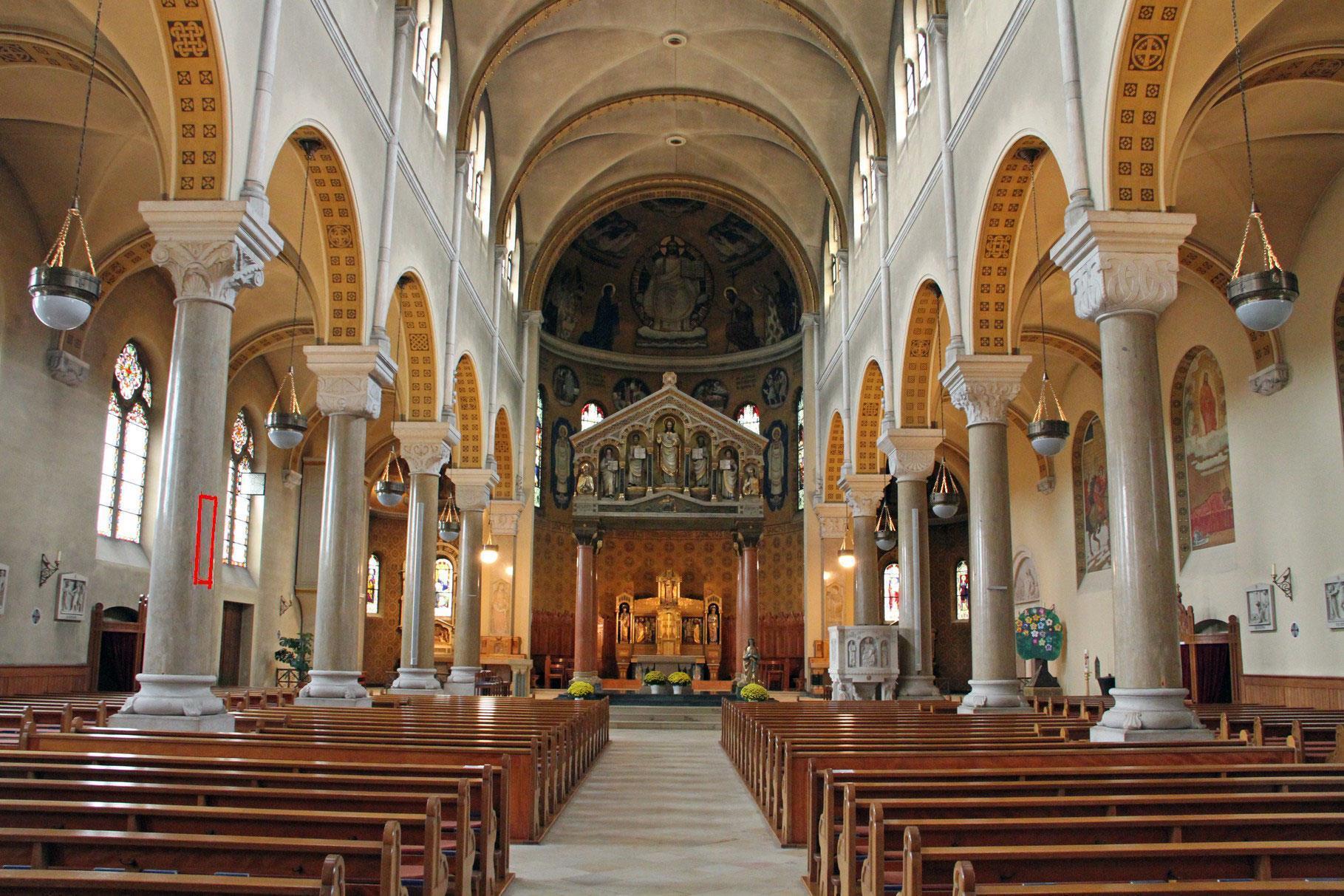
Figure 4
The Martinskirche, Olten, Switzerland(St. Martins Church) shows how inconspicuous a modern distributed column loudspeaker system can be visually. An orange rectangle is added to show where the loudspeakers, one on each building column, are located. Good intelligibility is provided in a properly reverberant acoustical environment. CD available10
Computer-Controlled Directional Characteristics
Duran Audio, in Holland, pioneered this concept around year 2002, with their Intellivox line of computer-controlled line-source loudspeaker systems. The basic concept is that each loudspeaker can be individually controlled in time, and thus also in phase, in level, and in frequency response.
Figure 5
Broadband control of line-source (column) loudspeakers’ directional characteristics by computer determined phase, time, level, and frequency response of individual loudspeakers in the multi-loudspeaker line source, from two manufacturers’ brochures.
Duran Audio became part of JBL Professional, and the reader is directed to JBL Professional’s website for more detailed information. In addition, Eastern Acoustics Works and Renkus-Heinz have informative websites on this type of loudspeaker. In practice, two or three loudspeakers in a given line have similar enough time, phase, level, and frequency-response requirements that permit some reduction in the number of digital filters, delay modules, d/a converters and analogue power output devices. The control possible goes beyond what is available from analogue technology.
My own experience with this technology is only as an observer at the Jerusalem Old City Evangelical Lutheran Church of the Redeemer. A fine baroque-modeled mechanical-action pipe organ with expert playing and musical direction and a fine choir, all in a rear balcony in a highly reverberant church, serve in services modeled directly after those J. S. Bach served at St, Thomas Church. Leipzig, and each service is a musical treat in every way. Spirited singing by the German-speaking main congregation, with additional; services in Arabic and English, are supplanted by a fine concert program. The late Elisabeth Roloff was the former music director, and she also taught Israeli musicians at the Jerusalem Academy of Music and Dance, where my friend, since he studied at Brandeis, the late composer Ben Zion Orgaad, also taught. Her own fine service and concert playing is reflected in the music of the two of her students that I have heard, Levi Sabin and Yuval Rabin, the latter the son of the late Israeli Prime Minister and also a terrific composer.10 Elisabeth Roloff’s successor is Gunther Martin Goettsche, and the musical excellence at the church has been maintained
The Jerusalem Church of the Redeemer had a distributed column loudspeakers system, with delay, and except for a few small dead-spots, notably in the two rear and front corners, intelligibility was good. Now these have been replaced with columns embodying this latest technology, and intelligibility is excellent throughout the entire church, with the loudspeakers still visible but less conspicuous
Note that music reinforcement contractors in Israel continue to rely on horn technology, and I have not heard this technology used in any music reinforcement. Also, one USA church that has a Klepper Marshall King central horn speech-reinforcement system decided to keep it after a test with the newer technology. I have yet to see frequency-response and polar-pattern measurements with the kind of detail shown in Figures 2 and 4 and also available to me concerning horn-loaded directional loudspeakers.
Challenges for the Future
Dynamic loudspeakers, the type usually used in line-source (column) loudspeakers, are also usable as microphones. This suggests the possibility of self-adjusting loudspeaker systems that emit “chirps” of broadband sound energy, and immediately revert to becoming microphone arrays that used the reflected energy from the room to analyze the room and determine where and how-much energy should be directed and where to minimize energy.
Figure 6
The basic concept of the self-analyzing loudspeaker system.
The second challenge relates to the fact that the computer-steered vertical line has computer-steering only in distance and for vertical angles, but not horizontally. Horizontally, the directional characteristics remain essentially those of the individual loudspeakers.
Figure 7
Directional Characteristics of two 4-inch loudspeakers used in line-source loudspeakers
Returning to Figure 4, note the red and dark-red areas on the side walls of three resulting sound level illustrations. These indicate sound levels on the side wall areas greater than those in seating areas. A detailed ray-diagram study of the reflected energy off these walls might indicate that there no problem; all the reflected energy that reaches listeners’ ears does so within 35 milliseconds. In cases where such “stray energy” would be a problem, then local sound-absorbing or sound-diffusing treatment would take care of the situation.
Before becoming part of JBL-Professional, Duran Audio had a product called the “Octagon” that had computer-controlled directional characteristics in the horizontal as well as vertical directions. It does not seem to be part of the current JBL catalogue however. Yet future development of this concept may be worthwhile.
Figure 8
Duran Audio Octagon
Notes and References
*Jacek Figwer, at Bolt Beranek and Newman, was acoustical consultant for the Duke University Chapel sound-reinforcement system. Also at BBN, I was consultant for the Rockefeller Chapel at U. of Chicago for the speech- reinforcement system, and Lawrence R. Kirkegaard the consultant at his firm for room-acoustics improvements.
1. Klepper, David L., a. “An Autobiographical Assessment of the Importance of the Early-to-Reverberant Sound-Energy Ratio, “Clarity,” in Speech Acoustics;” b. “Manfred Schroeder’s Frequency Shifter – an Audio Milestone;” c. “History Repeats Itself: Boston’s Hatch Shell, New York City’s Holy Apostles Church, Albert Einstein, Joseph Albo, and Variable Time.” This website; d. Kleiner, M., Klepper, D. L., and Torres, R., Worship Space Acoustics, J. Ross, Fort Lauderdale, Florida (2010). www.jrosspub.com
2. Clark, Keith, “A Conversation With SynAudCon Founders Don & Carolyn Davis.” This website
3. Klepper, David L., and Steele. Douglas W. “Constant Directional Characteristics from a Line-Source Array,” Journal of the Audio Engineering Society, 18:7, Aug. 1970, also in Sound Reinforcement, an AES Anthology, New York, 1978, p. D-21-25
4. Klepper, David L., “Reinforcing the Rabbi’s voice in Light of a Ban on Sabbath Electronic Reinforcement in Orthodox Synagogues.” This website
5. Klepper, David L. “Sound Systems in Reverberant Spaces for Worship,” Journal of the Audio Engineering Society, 18:7, Aug. 1970, also in Sound Reinforcement, an AES Anthology, New York, 1978, p. E-46-56.
6. P. H. Parkin and J. H. Taylor, ,,Speech reinforcement in St. Paul,s Cathedral,,,Wireless World 58:2, 58-61 and 58:3, 109-101 (1952), and reprinted inJAES, 54, p. 67-74 (2006)
7. L. L. Beranek, “Sound Systems for Large Auditoriums,” J. Acoust. Soc. Amer., 26, 661-675 (1954).
8. D. L. Klepper, “The Distributed Column Sound System at Holy Cross Cathedral, Boston, the Reconciliation of Speech and Music”, J. Acoust. Soc. Amer., 99:1, 417-425 (1996). The excellent 1875 Hook & Hastings organ in this Cathedral is discussed in B. Owen, The Organ in New England, The Sunbury, 1979, p.324-326, 600, 607, available from the Organ Historical Society, Richmond, VA,. But the organ is no longer neglected! (CDs are available.) A 2018-2019 complete building renovation saw the 1988 sound system equipment replaced, but retaining the same loudspeaker locations.
9. Dennis Landow, an audio-video DVD, To Hear the Music, www.tohearthemusic.com, also available from the C. B. Fisk Organ Company. Describes the design, construction, and installation of the new Harvard organ and is an excellent primer on organ building.
10. The CD, Organ Music from Israel, Yuval Rabin, organist, Mathis organ, St. Martinskirch, Olten, Switzerland, Ernst Bloch, Paul Ben-Haim, Karel Salomon, ShlomoDubonov, Haim Alexander, and Yuval Rabin, MDG (Germany) 606 1072-2, www.mdg.de. Higly recommended. Also an enjoyable and informative CD: Mendelssohn Bartholdy Organ Works, Mathis Organ, St. Marzellus, Gersau, MDG (Germany)906 1786-6, all Mendelssohn exceot a Yuval Rabin “Homage to Mendelssohn.” All organ registrations are listed with the notes for both CDs.
Appendix 1:
Appendix 2:
Addendum to Column Loudspeaker Paper, the “Infinite Line-Source”
Before the development of computer-steered line-source loudspeaker systems, but sometime after the development of the glass-fiber loaded Doug-Steele/Dave-Klepper approximation of constant directional characteristics, conceived was the concept of an infinite line-source loudspeaker system. One approach was originated by Larry and the author at Klepper Marshall King:
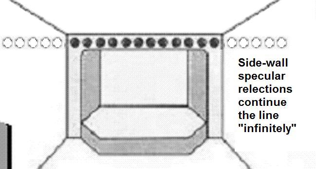

The Proscenium Horiontal Line concept was successfully applied at Peabody Conservatory’s Frieberg Concert Hall and at the Baltimore Aquarium’s Dolphin Theater.
A second approach was originated by the Church Engineering Group of the Latter-Day-Saints (Mormon) Church and applied in that church’s Chapels and Cultural Halls.
About the Author
David Lloyd Klepper is currently a student of Rabbinics at Yeshivat Beit Orot, Jerusalem, Israel, having moved to Israel in 1996 from his position as President of Klepper Marshall King, White Plains, NY, Acoustical Consultants, and as Adjunct Professor of Architectural Acoustics at City University, New York City. Before 1971 he was a senior consultant at Bolt Beranek and Newman, starting his consulting career there in May 1957. He received his SM and SB degrees in Electrical Engineering from MIT, and between times served as Assistant Audio-Radio Member of the PsyWar Board at Fort Bragg, NC, during the Korean conflict, leaving active duty as a 1st Lt. He provided acoustical advice for over 200 worship space buildings, including the National Presbyterian Church, Washington, DC, St. Thomas Church Fifth Avenue, New York City, the Capetown, South Africa, Anglican Cathedral, River Road Baptist Church, Richmond, Virginia, Young Israel of Southfield, Michigan, and Boston’s Holy Cross Cathedral. In this capacity, he was a pioneer in application of digital delay and electronic simulation of reverberation in worship spaces, and pew-back speech reinforcement. Publications include 40 papers in professional journals, a coauthor with Professor Kleiner and Father Rendell Torris of the book Worship Space Acoustics, JRosspub.com., and Editor of the two Sound Reinforcement Anthologies of the Audio Engineering Society. He is a fellow of both the Acoustical Society of America and the Audio Engineering Society, past Emeritus Board Certified member of the Institute of Noise Control Engineering, and a member of both the American Guild of Organists and the Organ Historical Society. He also belongs to a number of railroad and public transit interest organizations. You may contact Klepper at ddaveklepper1@gmail.com.