by Michael Rettinger – as Published in Re/p Magazine, August 1980
Since the late 1970’s recording studios have increasingly relied on so-called bass traps in their walls, ceilings and floors to control low-frequency absorption of sound. Broadly defined these bass traps are cavities or recesses of various dimensions, lined with one- or two-inch thick, vertically suspended, free hanging, glass fibre panels. The face of the opening is covered with a thin layer of material (grid cloth), and when installed as a pit in the floor is covered with a substantial mechanical grid capable of bearing typical floor loads.
Design Parameters
When the recess depth represents a quarter wavelength of the incident bass note (and odd multiples thereof) maximum sound absorption occurs at that frequency. The reason for this is that the air particle velocity is at a maximum at a quarter wavelength when reflected from a hard surface. At the quarter wavelength position the air molecules move at such a rapid rate, in and out of the horizontal layer, that a considerable amount of the acoustic energy of the wave is converted into heat within the frictional interstices of the material. Of course, other notes, too, are thus absorbed as their waves pass between the spaced glass fibre panels, striking the soft bottom layer and returning again through the highly absorbent environment. The table below gives the quarter wavelength of various bass notes, and thus the required trap depth for this frequency of “suppression:”
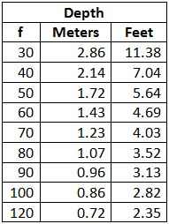
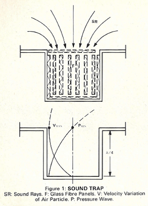
When a band of bass notes is to be absorbed, the bottom of the pit should be slanted. As an example, when the octave between 40 and 80 Hertz is to be expunged from the incident signal, one end of the cavity should have a depth of 7 feet and the other end should have one of 3.5 feet. For such wide-band absorption the cross-sectional area of the trap should be larger than when only one sinusoid is to be effectively absorbed. The very high absorption capability of such a glass-fibre-lined floor, wall or ceiling chamber, as far as the whole room is concerned, is due to the fact that precisely where the air-particle velocity of the reflected wave is at a maximum, the sound pressure is at a minimum, being 90 degrees out of phase with the particle velocity. The reason for this is that at the bottom of the pit the air particles cannot move at all, they are facing an immobile barrier; while at the same time a doubling of the pressure amplitude results. The face of the trap, then, represents a vacuum, drawing “sound rays” into the cave, which otherwise would have travelled elsewhere, as diagrammatically illustrated in Figure 1:
Bass Trap Purpose
The purpose of a bass trap is twofold – to absorb floor reflections for the bass notes of the drums and violas and other instruments with predominantly low-frequency output (when the instrument is positioned over the trap), and to lower the music level of these bass notes as they arrive in the vicinity of adjacent instruments. The primary use, then, is to prevent bass notes from leaking into microphones where they are unwanted, in multitrack recording situations. Another purpose is to provide greater acoustic comfort for the other players in the studio. Drum notes, for instance, can reach a sound pressure level of 100 dB at a distance of one meter or three feet, and violas, too, can generate acoustically uncomfortable levels, particularly for nearby violinists. An incidental purpose of a trap is to absorb really low notes generated anywhere in the studio.
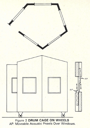
Where bass frequencies are not controlled by traps there is often a need to segregate certain musicians. Drummers are placed in drum cages (Figure 2) and pianos in similar enclosures, away from the band, often to the discomfort of these performers.
From the experiences of many recording engineers, the use of “flats” or “gobos” between instrument sections to produce sufficiently clean tracks for multitrack recording has been unsatisfactory. This is often due to the ability of the sound to creep and leak around and under poorly, inexpertly or cheaply designed partitions, many of which are built off the floor, on wheels, and are not thick or high enough. Also, these devices do not allow the performer to see others in adjacent areas for allowing better timing because space dividers generally do not have windows. As additional arguments against this kind of leakage control, some engineers consider flats too cumbersome to adjust, and when not in use they take up valuable floor space unless storage was planned for in the design stage of the studio. Finally, as hand-crafted items, such units are expensive, and sometimes obscure the view of the mixer intent on watching the performers.
In this connection, the writer would like to cite an experience he had .in 1943 when Columbia Pictures, in Hollywood, decided to make the “AI Jolson Story,” with Larry Parks. Al Jolson had been commissioned to personally sing the important songs in “The Jazz Singer.” He insisted on rendering his vocals from within the orchestra, because as a stage performer he had always been surrounded by musicians. To accommodate him a glass booth was constructed with a heavily absorbent floor and ceiling, earphones were offered to him so that he could sing in synchronism with the instrumental music. He would not wear them. Surprisingly, the very little sound which filtered through the glass was enough for him to stay in time, although it could not be heard on his track.
Disadvantages of Bass Traps
There are two disadvantages connected with the use of bass traps. One lies in the music sounding somewhat less good, that is somewhat less lively, rich, and full. The second relates to the performer positioned over a bass trap feeling somewhat uncomfortable, as if he were suspended in mid-air, without any reinforcing sounds about him.
The physics of sound will enable a more detailed look at these effects. In 1931, G. W. Steward, Professor of Physics at the State University of Iowa, published the “Acoustic Uncertainty Principle.”* It is similar to Heisenberg’s uncertainty principle in quantum mechanics. By the latter theorem one will never be able to see an electron under a microscope, because the impact of the light ray upon the sub-atomic particle moves it so much that the reflected light ray in the eyepiece can show up as only a blur. By the acoustic uncertainty principle we face a similar inability to recognize the components of a complex sound wave. Stated mathematically, both the Heisenberg and the Steward uncertainty principle may be expressed as follows:
Δf x Δt = 1
where f refers to the frequency in the acoustic case, and to the total energy of the moving particle in the case of quantum mechanics; where t represents the time in both cases, while delta is the class interval.
As an example of the acoustic principle of uncertainty, consider a musical note. One does not hear a single frequency tone but a pulse which by Fourier analysis is found to consist of a number of sinusoids. There is a frequency f1 of maximum intensity and a range of higher and lower frequencies with different intensities. When one tries, aurally, to identify f1 there is difficulty in recognizing it because of the presence of other components. As an example, assume we wish to determine a 1,000 Hz f1 with 1 per cent accuracy. This means that one has to evaluate f1 within 10 Hertz. By the acoustic principle of uncertainty, the required time interval is .1 seconds, because 20 x .1 = 1. When the frequency interval is to be only 3.3 Hertz, the required time interval becomes .3 seconds, because 3.3 x .3 = 1. In other words, the accuracy of the frequency definition increases with time. But there is no way in an anechoic environment to increase this time, because there are no “fusing” reflections. However, by placing a reflective surface near an instrument, this time interval is increased by the minutely delayed reflection; besides, intensity at the ear of the performer. Musicians are very conscious of this effect and call it “attack” or “tonal force:” This is also one of the reasons why we like to sing in the shower, although in this case we have also the effect of a longer reverberation time.
What about acoustic comb filter effects when we have a reflecting surface near an instrument? Too, what about the sounding board of a piano which reflects the action of the strings? .Or better yet, what about the twenty violins in a symphony orchestra? At the microphone their signals are all out of phase with each other, and yet their rendition is better than that of a single violin because of these phase relationships. Anecdotally, at the beginning of sound-on-film recording a producer thought he could save money by having the recordist turn up the amplifier level 13 dB in imitation of the signal strength of 20 violins compared to that of one violin. The effect was very discouraging when the photographed scene showed a violin ensemble where the distant performers were not musicians but mimicking extras. So, we cannot ignore the facts which have made music rich in appeal, even when acoustic spectrometry appears to show an anomaly. We have a great deal to learn about the ear and, especially, about the human brain which analyzes what we hear.
A theorist might object to such bass traps for reasons other than those already mentioned. He might say that a studio with such a trap is no longer a room, a three dimensional enclosure, because the sound absorbent pit represents a discontinuity of the bounded space, where sound can enter but not return. By the G. Millington equation, he might say, it is not even possible to calculate the reverberation time of the studio. The reasoning would be that the equation contains the term:
S log(1-a)
where S is the cross-sectional area of the trap and a is its (unity) absorption coefficient, which term would become minus infinity. Actually, by our method of absorption measurements, a would turn out to be larger than unity, for the reason that some of the normally diffused signal would be “sucked” into the hole, which sound rays otherwise would travel in straight lines about the enclosure. Lack of uniform distribution of the sound energy would result in a nonexponential decay of the signal on sudden stoppage. These are the fine points, which in studios with reverberation periods of .2 to .4 seconds would probably not be noticed by the majority of performers. They are presented here for the sake of analysis of the subject of bass traps.
*Steward, G. W., “Problems Suggested By An Uncertainty Principle In Acoustics,” Jl. Acoustical Society of America, Vol. 2, No.3, January 1931, page 325.
About the Author*
Michael Rettinger, a specialist in the field of architectural acoustics, died in 1985 February. Born in 1905 in Munich, West Germany, Rettinger studied physics in the U.S. at the University of California at Los Angeles where he earned B.A. and M.A. degrees.
In 1936 he joined the film recording section of RCA in Hollywood as an acoustics engineer and remained with the company until 1965 when he chose early retirement. Active as a consultant on acoustics, Rettinger also wrote six books and numerous published articles on acoustics and electroacoustics. His books, published by Chemical Publishing Company, New York, include: Applied Architectural Acoustics, Practical Electroacoustics, Architectural Acoustics, Acoustics, Acoustical Design and Noise Control, and Studio Acoustics.
A fellow of the SMPTE, Rettinger was also a member of the Academy of Motion Picture Arts and Sciences, the Institute of Noise Control Engineering, and a life member of the Audio Engineering Society.
*As posted in the Journal of the Audio Engineering Society, Volume 32, No. 1-2 (Jan-Feb 1986)
