 Compression drivers and the horns that comprise the horn loudspeaker system have been a part of the audio industry from the very beginning of product development in sound reinforcement systems.
As is true for cone loudspeakers, most of the early development in horn loudspeakers began when sound was first put to picture back in the 1930s when the first “talking films” were released.
Since that time, compression driver technology coupled with horn development advances have been in the areas of materials science allowing improvements in power handling capacity, lower distortion levels, and improvement of directional characteristics of the horn devices.
The chief difference in output when cone loudspeakers are compared with horn loudspeakers is the relative efficiency of the system.
Cone loudspeakers are known as direct radiators due to the fact that they are an electromechanical moving system that couples via the cone directly to the air around it. A great deal of power is needed to move that cone and thereby move the air around it, so it is not very efficient system.
Low efficiency in this case means that with every 100 watts of input power, a cone loudspeaker may only produce 2 or 3 watts of acoustical power output. In comparison, a horn loudspeaker with a midrange compression driver efficiency of 25 to 30 percent will require as little as 10 or 12 watts of power input to produce the same 2 or 3 watts of acoustical power output – a vast improvement in efficiency.
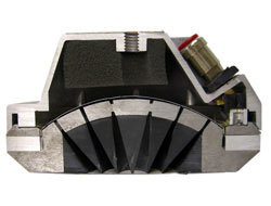
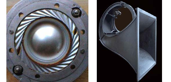
Details of a high-frequency compression driver are shown in Figure 1. The driver consists of a thin diaphragm which is placed about 0.02 inch (0.5 mm) from the phasing plug.
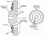
Figure 1: Details of a compression driver. Above/right we see a section view, and next to it, a rear view.
The voice coil at the edge of the diaphragm is immersed in a strong magnetic field. The spherical surface of the phasing plug has a series of annular (circular) slits that extend through the body of the driver to the driver’s exit.
The total area of the slits at the diaphragm side of the driver is approximately one-eighth to one-tenth of the area of the diaphragm itself. It is the area difference which creates the so-called loading factor of the driver, enabling the impedance of the moving system to be properly matched to the impedance of the throat of the horn.
The driver is optimized to produce very high pressures with wide bandwidth at its exit.
Diaphragm materials include aluminum, titanium, and beryllium for drivers with extended frequency response. Phenolic resin impregnated linen materials are used for those drivers intended for limited bandwidth, high power applications.
The phase plug also acts to equalize the path lengths from the surface of the diaphragm to the output of the driver.
In this function it promotes extended high-frequency response by minimizing destructive interferences at high frequencies.
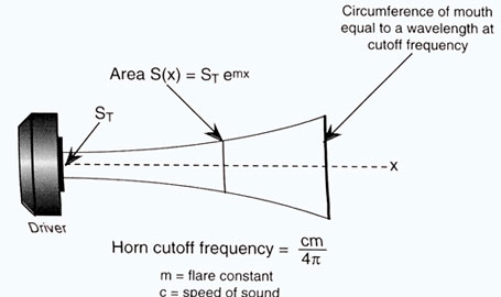
The driver is attached to the horn (Figure 2), which provides a smooth transition from the small area at the throat to the large area at the mouth. It functions as a continuous acoustical transformation, providing an efficient impedance match with the free-air load seen at the mouth.
Essentially, the horn converts a high-pressure/low-volume-velocity relationship at the throat to a high-volume-velocity/low-pressure relationship at the mouth. Early horn designers always used an exponential profile in their horns, since that guaranteed the best overall loading.
Figure 2: Two making one, a compression driver and its companion exponential horn.
The cut-off frequency establishes the lower frequency limit of horn performance. However, in order to attain the desired degree of low frequency performance, the horn’s mouth must be of sufficient size.
A general rule is that the circumference of the mouth should be at least one wavelength at the cutoff frequency if good loading is to extend down to that frequency.
As an example, a horn designed with a cut-off frequency of 500 Hz should have a mouth circumference of about 2 feet. High-quality compression drivers fall into two general categories:
Diaphragm Diameter—————-Continuous Power Rating
1-inch to 2-inch small format———–25 watts to 50 watts
3-inch to 4-inch large format———–75 watts to 100 watts
These values are approximate and represent a norm in the industry, in general, for a given output level on a given horn, the larger the diameter of the diaphragm the lower the distortion will be. The small format drivers normally have a 1-inch (25-mm) exit diameter, the 3-inch (76-mm) drivers and the 4-inch (100-mm) drivers normally have 1.5-inch (38-mm) or 2-inch (50-mm) exit diameters.
In the real world of loudspeaker specification for professional activities, there is no substitute for actual measurements of drivers mounted on their intended horns. The standard today is to state the mid-band sensitivity of the horn-driver combination, with a power input of one watt and the measurement made at a distance of one meter.
This discussion is excerpted from JBL Audio Engineering For Sound Reinforcement by John Eargle and Chris Foreman. It is distributed by Hal Leonard Publishing.
A Bit More About Drivers…
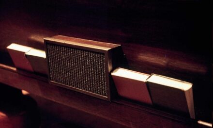
The Western Electric we555 compression driver pictured below (left) looks fairly modern, no?
Believe it or not, however, this unit was introduced in 1928, and enjoyed a long life, finding primary use with cinema sound systems, which were in their infancy.
Often, the we555 was used with the Western Electric 15B horn pictured below (right), and with a low-frequency loudspeaker, was positioned behind the screen – the same as is done today.
Many think the sound quality of the we555 still hasn’t been topped. It initially had a maximum power handling specification of 5 watts, which went up a bit over the years as new versions were introduced. The diaphragm also underwent a number of changes.