by John Eargle, James B. Lansing Sound, Inc. – as published in R-e/p Magazine October, 1981
Most practical loudspeaker systems do not exhibit minimum phase performance. Rather, we might view their response as the combination of an ideal system whose performance is minimum phase, operating in series with an all-pass (no attenuation) network providing the phase error observed in the system’s response. It is this phase error that we would like to minimize. As long as any loudspeaker behaves like a band-pass filter, it will exhibit a unique phase response that is related to its amplitude response. If the loudspeaker is ideal, then the phase response will exhibit the minimum possible deviation from flat phase response – hence the term minimum phase.
A more convenient way to examine the same phenomenon is through the group delay response of the system. Group delay is defined as minus the rate of phase (φ) change with respect to frequency (ω):
It is plotted by taking the slope of the observed phase response with respect to frequency.
Designing a minimum phase multi-way system is not easy, and there are three factors that must be carefully controlled:
- Physical alignment of transducers and components on the baffle. The alignment of acoustic centers may be correct for only one bearing angle.
- Inherent transducer response. The use of drivers and components in the region of their natural cutoff points complicates the design.
- Dividing network characteristics. Some circuit configurations that could be ideal from a driver protection point of view, may be incompatible with the minimum phase concept.
The juggling of these three variables is tricky and, in the process of optimizing time-domain response, a design engineer might not give due attention to all the trade-offs involved. For example, a number of the stepped baffle arrangements popular in consumer system design a few years ago provided essentially minimum phase response, but at the expense of troublesome diffraction and reflections at the complex baffle boundaries.
Audible Thresholds
While minimum phase systems are correct from a theoretical point; the question must be raised as to their audible superiority over systems which exhibit some residual error. Blauert and Laws1 in West Germany carried out experiments published in 1978. In these experiments they identified the audible thresholds at several different frequencies, for various amounts of all-pass time delay. For the tests, Blauert and Laws used electrostatic headphones exhibiting a low value of non-minimum phase response. In general, Blauert and Laws determined that group delay errors superimposed on the headphones could best be detected with impulsive sounds presented under anechoic conditions.
The sensitivity thresholds for this signal input condition are shown in Figure 1. Plotted on this same graph are the relative group delay characteristics of three monitor systems: the Altec 604 as “time aligned” by UREI; the JBL 4331; and the new JBL 4430 Biradial system. Note that all three systems fall well below the Blauert and Laws criteria for audibility of delay effects.
Inasmuch as the Blauert and Laws studies were based on impulsive signals played back anechoically, the assumption may be “made that musical signals played back in typical listening rooms would be somewhat less stringent in the required degree of time-domain accuracy. In any event, the three monitor systems described in Figure 1 meet criteria far more stringent than will normally be required.
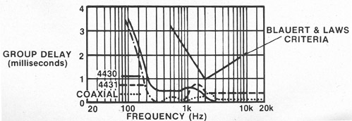
Taking a closer look at Figure 1, we can comment on the differences between the systems. The group delay curve for the 4430 shows that the high-frequency acoustic center is in front of the LF portion of the system by some 500 microseconds. In the case of the 4331, the 11.5-inch 2312 high-frequency horn places the acoustic center of the high-frequency driver about 350 microseconds behind the low-frequency driver. The bump in the curve at 1500 Hz is due both to irregular amplitude response, and to network characteristics.
In the case of the time-compensated Altec 604, we note that the acoustic centers of high- and low-frequency sections are precisely aligned. The small bumps at 500 Hz and just above 2000 Hz are likely due to irregular amplitude response in these areas. Below 250 Hz, all the group delay curves show a marked increase in delay. This is due to the inherent low-frequency roll-off of the systems.
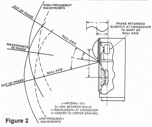
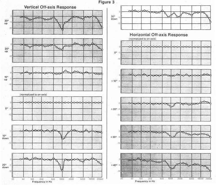
In the design of the JBL 4430 (and 4435 ), the step in the group delay curve was used to advantage: it made possible an optimization of vertical off-axis response for listeners located on or above the normal axis. Details of this offset are shown in Figure 2, and the resulting normalized response curves in Figure 3. Because these systems are not coaxial, there are bound to be certain vertical off-axis angles that will exhibit phase cancellations. As the curves in Figure 3 for 10° and 20° upward show, smooth response can be maintained over a wide vertical area because of the time offset.
If one accepts the Blauert and Laws data, then time¬domain alignment takes its place in the general design equation as a variable to be balanced along with flat axial response, smooth power response and a concern for proper driver protection.
References
1). J. Blauert P. Laws, “Group Delay Distortions in Electroacoustical Systems,” Journal of the Acoustical Society of America, Vol. 63, pp. 1478-1483 (May 1978).